MSPM0L1345: Current consumption of idle I2C interface - while in SLEEP or STANDBY

Part Number: MSPM0L1345
Other Parts Discussed in Thread: LP-MSPM0L1306, ENERGYTRACE, MSPM0L1306

Tool/software:

I could not find any documentation on the current consumption burden of keeping the I2C configured while we are trying to keep compliant to the specification of 1uA of standby current.

It is critically important that we understand if there is any additional current consumption from keeping the I2C active, perhaps a better word is "configured" during the low power RTC standby.

Within this question, the I2C (pins 4 & 5 of the 1345), would not be communicating or connected to a "mother" device.  It would and should have ESD protection on those IOs of course. Any suggestion on preferred devices or configuration of ESD protection would be most appreciated.

The pullup resistors would reside on the mother device.

Once connected to the mother device, the processor would be alerted via interrupt configuration presumably.

THANK YOU

  • I should have mentioned, the configuration would be STANDARD speed, and wanting to implement either SM/PMbus commands.

  • Hi Roger,
    I recommend looking over the 3.1 PCB Design Guidelines from the EMC Improvement Guide for MSPM0 for better guidance on ESD protection (I also recommend looking over the LP-MSPM0L1306 for reference, or other Reference Designs in the L1345 product page.) As for the current consumption of the I2C when in STANDBY1, let me ask around

    Best Regards,

    Diego Abad

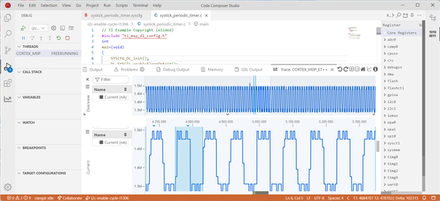
  • Since this question also came up in another thread, I set up a simple-minded experiment which simply toggled the I2C ACTIVE (enable) bit periodically. EnergyTrace indicated the enabled/disabled difference at about 120uA

    Specifically, I started with the SysTick example for the MSPM0L1306 and I

    1) Changed the SysTick period to 50ms (big enough to see, small enough to get many samples)

    2) Configured the I2C unit as Master, 100kHz, on PA0/1 using the Launchpad's on-board pullups. Nothing was connected to the pins.

    3) Removed the LED code and (to be sure) removed the LED jumpers. I also removed the TXD/RXD jumpers from J101.

    4) The low-power mode was SLEEP0 (unchanged). 

    The entire program:

    // TI Example Copyright (elided)
    #include "ti_msp_dl_config.h"
    int 
    main(void)
    {
        SYSCFG_DL_init();
        DL_SYSCTL_enableSleepOnExit();
        while (1) {
            __WFI();
        }
    }
    
    void 
    SysTick_Handler(void)
    {
        if (DL_I2C_isControllerEnabled(I2C_0_INST))
        {
            DL_I2C_disableController(I2C_0_INST);
        }
        else 
        {
            DL_I2C_enableController(I2C_0_INST);
        }
    }
    

    EnergyTrace showed:

    I see a square wave of period 100ms, so I'm pretty sure that's the enable-cycling. Ignoring the "blips", EnergyTrace reported [hover text, not shown] 1426100 for the high side and 1306600 for the low side. The difference would be 119500, or about 120uA.

    There are undoubtedly refinements possible, but this would seem to provide an order of magnitude.

  • thanks this was very helpful.