This thread has been locked.

If you have a related question, please click the "Ask a related question" button in the top right corner. The newly created question will be automatically linked to this question.

MCU-PLUS-SDK-AM243X: Ethernet/Ip - Ethernet Link Interface Control

Part Number: MCU-PLUS-SDK-AM243X
Other Parts Discussed in Thread: DP83826E, DP83869

Tool/software:

Hi,

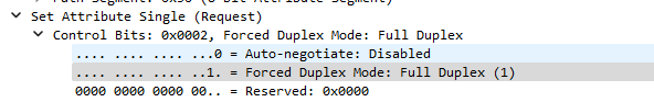
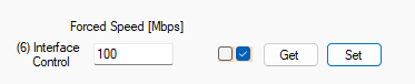
I'm trying to set 100Mb - Full duplex through master ethernet/ip.

When I set 10mb - Full Duplex, i do not have any problems.

When I try to set 100Mb - Full Duplex, it seems that PHY stops responding, but application still working well.

This feature is required by ODVA certification. 

Do you have any suggestion? I'm using DP83826E physical layer and drivers taken from SDK 11.08.

Bye

  • Hi,

    After debugging I have seen that the problem is related when Auto NEG off is set in register on PHY. While I think that Windows support only Auto NEG ON with 100M - Full Duplex.

    The test requires to have Auto NEG OFF with 100M - Full Duplex. Is there a way to test this feature with master ethernet/ip on windows(I'm using Hilsher Tool).

    Bye.

    Stefano

  • Hi Stefano,

    I recommend using a network switch between your test PC and your target device. This approach would solve connectivity issues even when your test PC cannot detect the target's network interface if it's configured to a fixed speed mode. The switch should be able to handle the proper routing between the devices.

    Best regards,
    Pourya

  • Hi Pourya,

    I am using a Switch between my DUT and PC(Master Ethernet/IP).

    When DUT starts, PHY is 100M - FD - Auto Neg ON and all works well.

    When I change to 10M - Full Duplex link goes down for few seconds and then turns on and all works.

    But when I try to change to 100M (Auto Neg Always off), link goes down for minutes and comunication stops working but application still working. 

    In case I change configuration on switch, PHY goes up and works.

    Do you have some suggetions to avoid issue with 100M and auto neg OFF, without changing settings on switch?

    I am changing settings through class 0xF6

  • Hi Stefano,

    I tried to reproduce what you have described on my side, but it works for me without any problem.
    Are you using a custom board, or are you using the TI's AM243x-LP board?

    Best regards,
    Pourya

  • Hi Pourya.

    No, I am using custom HW with DP83826E PHY and CUST_PHY_DP83826E.c file taken from SDK 11.08.

  • Hi Stefano,

    could you please share the syscfg file and also if available the UART log from your device?
    The UART log would be helpful to see what messages regarding the PHY are printed at startup.

    Best regards,
    Pourya

  • Hi Pourya,

    Here what you've asked. In my case if I disable auto neg on module, for working I have to fix speed and mode on switch.


    /**
    * These arguments were used when this file was generated. They will be automatically applied on subsequent loads
    * via the GUI or CLI. Run CLI with '--help' for additional information on how to override these arguments.
    * @cliArgs --device "AM243x_ALV_beta" --part "ALV" --package "ALV" --context "r5fss1-0" --product "INDUSTRIAL_COMMUNICATIONS_SDK_AM243x@09.02.00"
    * @v2CliArgs --device "AM2432" --package "FCBGA (ALV)" --context "r5fss1-0" --product "INDUSTRIAL_COMMUNICATIONS_SDK_AM243x@09.02.00"
    * @versions {"tool":"1.22.0+3893"}
    */
    
    /**
     * Import the modules used in this configuration.
     */
    const flash       = scripting.addModule("/board/flash/flash", {}, false);
    const flash1      = flash.addInstance();
    const crc         = scripting.addModule("/drivers/crc/crc", {}, false);
    const crc1        = crc.addInstance();
    const gpio        = scripting.addModule("/drivers/gpio/gpio", {}, false);
    const gpio1       = gpio.addInstance();
    const gpio2       = gpio.addInstance();
    const gpio3       = gpio.addInstance();
    const gpio4       = gpio.addInstance();
    const gpio5       = gpio.addInstance();
    const gpio6       = gpio.addInstance();
    const gpio7       = gpio.addInstance();
    const gpio8       = gpio.addInstance();
    const ipc         = scripting.addModule("/drivers/ipc/ipc");
    const pruicss     = scripting.addModule("/drivers/pruicss/pruicss", {}, false);
    const pruicss1    = pruicss.addInstance();
    const ethernetip  = scripting.addModule("/industrial_comms/ethernetip/ethernetip", {}, false);
    const ethernetip1 = ethernetip.addInstance();
    const debug_log   = scripting.addModule("/kernel/dpl/debug_log");
    const mpu_armv7   = scripting.addModule("/kernel/dpl/mpu_armv7", {}, false);
    const mpu_armv71  = mpu_armv7.addInstance();
    const mpu_armv72  = mpu_armv7.addInstance();
    const mpu_armv73  = mpu_armv7.addInstance();
    const mpu_armv74  = mpu_armv7.addInstance();
    const mpu_armv75  = mpu_armv7.addInstance();
    const mpu_armv76  = mpu_armv7.addInstance();
    const mpu_armv77  = mpu_armv7.addInstance();
    const mpu_armv78  = mpu_armv7.addInstance();
    const mpu_armv79  = mpu_armv7.addInstance();
    const mpu_armv710 = mpu_armv7.addInstance();
    const mpu_armv711 = mpu_armv7.addInstance();
    const mpu_armv712 = mpu_armv7.addInstance();
    const mpu_armv713 = mpu_armv7.addInstance();
    const mpu_armv714 = mpu_armv7.addInstance();
    const mpu_armv715 = mpu_armv7.addInstance();
    const timer       = scripting.addModule("/kernel/dpl/timer", {}, false);
    const timer1      = timer.addInstance();
    
    /**
     * Write custom configuration values to the imported modules.
     */
    flash1.$name                         = "CONFIG_FLASH0";
    flash1.peripheralDriver.$name        = "CONFIG_OSPI0";
    flash1.peripheralDriver.OSPI.$assign = "OSPI0";
    
    crc1.$name = "CONFIG_CRC0";
    
    gpio1.$name          = "ETH_100BT1_EN";
    gpio1.pinDir         = "OUTPUT";
    gpio1.defaultValue   = "1";
    gpio1.GPIO_n.$assign = "PRG1_PRU1_GPO18";
    
    gpio2.$name          = "ETH_100BT1_RST_N";
    gpio2.pinDir         = "OUTPUT";
    gpio2.defaultValue   = "1";
    gpio2.GPIO_n.$assign = "PRG1_PRU1_GPO16";
    
    gpio3.$name          = "ETH_100BTX_RST_N";
    gpio3.pinDir         = "OUTPUT";
    gpio3.defaultValue   = "1";
    gpio3.GPIO_n.$assign = "PRG0_PRU0_GPO18";
    
    gpio4.$name          = "ETH_100BTX_RMII";
    gpio4.pinDir         = "OUTPUT";
    gpio4.GPIO_n.$assign = "PRG1_PRU1_GPO19";
    
    gpio5.$name          = "ETH_100BTX_INT";
    gpio5.pinDir         = "OUTPUT";
    gpio5.GPIO_n.$assign = "PRG0_PRU0_GPO19";
    
    gpio6.$name          = "PRG1_MDIO0_MDC";
    gpio6.GPIO_n.$assign = "PRG1_MDIO0_MDC";
    
    gpio7.$name          = "PRG1_MDIO0_MDIO";
    gpio7.GPIO_n.$assign = "PRG1_MDIO0_MDIO";
    
    gpio8.$name          = "GPIO_CB";
    gpio8.rx             = true;
    gpio8.GPIO_n.$assign = "PRG1_PRU1_GPO2";
    
    ipc.r5fss0_1     = "NONE";
    ipc.r5fss1_1     = "NONE";
    ipc.m4fss0_0     = "notify";
    ipc.vringMsgSize = 512;
    
    ethernetip1.$name                                = "CONFIG_ETHERNETIP0";
    ethernetip1.instance                             = "ICSSG0";
    ethernetip1.phyAddr0                             = 1;
    ethernetip1.phyAddr1                             = 2;
    ethernetip1.icss_emac[0].$name                   = "CONFIG_ICSS_EMAC0";
    ethernetip1.icss_emac[0].mode                    = scripting.forceWrite("SWITCH");
    ethernetip1.icss_emac[0].phyToMacInterfaceMode   = scripting.forceWrite("MII");
    ethernetip1.icss_emac[0].learningEnable          = true;
    ethernetip1.icss_emac[0].halfDuplexEnable        = true;
    ethernetip1.icss_emac[0].txTaskPriority          = 20;
    ethernetip1.icss_emac[0].rxTaskPriority          = 20;
    ethernetip1.icss_emac[0].linkTaskPriority        = 24;
    ethernetip1.ethphy1[0].mdioManualModeLinkPolling = scripting.forceWrite("Polling");
    ethernetip1.ethphy1[0].$name                     = "CONFIG_100BTX";
    ethernetip1.ethphy1[0].name                      = "CUSTOM";
    ethernetip1.ethphy1[0].customDeviceName          = "DP83826E";
    ethernetip1.ethphy2[0].mdioManualModeLinkPolling = scripting.forceWrite("Polling");
    ethernetip1.ethphy2[0].$name                     = "CONFIG_TJA1101";
    ethernetip1.ethphy2[0].name                      = "CUSTOM";
    ethernetip1.ethphy2[0].customDeviceName          = "tja1101";
    ethernetip1.PRU_ICSSG0_IEP.$assign               = "PRU_ICSSG0_IEP0";
    ethernetip1.PRU_ICSSG0_IEP.EDC_LATCH_IN0.$used   = false;
    ethernetip1.PRU_ICSSG0_IEP.EDC_SYNC_OUT0.$used   = false;
    
    pruicss1.$name                           = "CONFIG_PRU_ICSS0";
    pruicss1.iepSyncMode                     = true;
    ethernetip1.icss                         = pruicss1;
    pruicss1.AdditionalICSSSettings[0].$name = "CONFIG_PRU_ICSS_IO0";
    
    debug_log.enableUartLog            = true;
    debug_log.enableCssLog             = false;
    debug_log.enableSharedMemLog       = true;
    debug_log.enableSharedMemLogReader = true;
    debug_log.uartLog.$name            = "CONFIG_UART_CONSOLE";
    debug_log.uartLog.UART.$assign     = "USART0";
    
    const uart_v0_template  = scripting.addModule("/drivers/uart/v0/uart_v0_template", {}, false);
    const uart_v0_template1 = uart_v0_template.addInstance({}, false);
    uart_v0_template1.$name = "drivers_uart_v0_uart_v0_template0";
    debug_log.uartLog.child = uart_v0_template1;
    
    mpu_armv71.$name             = "CONFIG_MPU_REGION0";
    mpu_armv71.allowExecute      = false;
    mpu_armv71.attributes        = "Device";
    mpu_armv71.accessPermissions = "Supervisor RD+WR, User RD";
    mpu_armv71.size              = 31;
    
    mpu_armv72.$name             = "CONFIG_MPU_REGION1";
    mpu_armv72.accessPermissions = "Supervisor RD+WR, User RD";
    mpu_armv72.size              = 15;
    
    mpu_armv73.$name             = "CONFIG_MPU_REGION2";
    mpu_armv73.baseAddr          = 0x41010000;
    mpu_armv73.size              = 15;
    mpu_armv73.accessPermissions = "Supervisor RD+WR, User RD";
    
    mpu_armv74.baseAddr          = 0x70000000;
    mpu_armv74.size              = 21;
    mpu_armv74.accessPermissions = "Supervisor RD+WR, User RD";
    mpu_armv74.$name             = "CONFIG_MPU_REGION3_SRAM";
    
    mpu_armv75.baseAddr   = 0x80000000;
    mpu_armv75.size       = 31;
    mpu_armv75.attributes = "NonCached";
    mpu_armv75.$name      = "CONFIG_MPU_REGION4_DDR";
    
    mpu_armv76.baseAddr = 0x80000000;
    mpu_armv76.$name    = "CONFIG_MPU_REGION5_DDR_ICSS";
    mpu_armv76.size     = 25;
    
    mpu_armv77.attributes = "NonCached";
    mpu_armv77.$name      = "CONFIG_MPU_REGION6_DDR_DATA";
    mpu_armv77.size       = 20;
    mpu_armv77.baseAddr   = 0x83800000;
    
    mpu_armv78.size       = 20;
    mpu_armv78.attributes = "NonCached";
    mpu_armv78.$name      = "CONFIG_MPU_REGION7_DDR_BSS";
    mpu_armv78.baseAddr   = 0x83900000;
    
    mpu_armv79.attributes = "NonCached";
    mpu_armv79.$name      = "CONFIG_MPU_REGION8_DDR_PNIP";
    mpu_armv79.baseAddr   = 0x82000000;
    mpu_armv79.size       = 23;
    
    mpu_armv710.$name    = "CONFIG_MPU_REGION3_DDR_HEAP";
    mpu_armv710.size     = 23;
    mpu_armv710.baseAddr = 0x83000000;
    
    mpu_armv711.$name      = "CONFIG_MPU_REGION3";
    mpu_armv711.baseAddr   = 0x70000000;
    mpu_armv711.size       = 16;
    mpu_armv711.attributes = "Cached+Sharable";
    
    mpu_armv712.$name        = "CONFIG_MPU_PRU_ICSS";
    mpu_armv712.baseAddr     = 0x30080000;
    mpu_armv712.size         = 19;
    mpu_armv712.attributes   = "Device";
    mpu_armv712.allowExecute = false;
    
    mpu_armv713.$name        = "CONFIG_MPU_REGION12";
    mpu_armv713.baseAddr     = 0x88000000;
    mpu_armv713.size         = 26;
    mpu_armv713.attributes   = "NonCached";
    mpu_armv713.allowExecute = false;
    
    mpu_armv714.$name        = "CONFIG_MPU_REGION13";
    mpu_armv714.baseAddr     = 0x8C000000;
    mpu_armv714.size         = 13;
    mpu_armv714.attributes   = "NonCached";
    mpu_armv714.allowExecute = false;
    
    mpu_armv715.$name        = "CONFIG_MPU_REGION14";
    mpu_armv715.baseAddr     = 0x701D0000;
    mpu_armv715.size         = 16;
    mpu_armv715.attributes   = "NonCached";
    mpu_armv715.allowExecute = false;
    
    timer1.$name         = "CONFIG_TIMER0";
    timer1.startTimer    = true;
    timer1.timerCallback = "OSAL_FREERTOS_callbackTimer";
    timer1.TIMER.$assign = "DMTIMER1";
    
    /**
     * Pinmux solution for unlocked pins/peripherals. This ensures that minor changes to the automatic solver in a future
     * version of the tool will not impact the pinmux you originally saw.  These lines can be completely deleted in order to
     * re-solve from scratch.
     */
    flash1.peripheralDriver.OSPI.CLK.$suggestSolution            = "OSPI0_CLK";
    flash1.peripheralDriver.OSPI.CSn0.$suggestSolution           = "OSPI0_CSn0";
    flash1.peripheralDriver.OSPI.DQS.$suggestSolution            = "OSPI0_DQS";
    flash1.peripheralDriver.OSPI.D7.$suggestSolution             = "OSPI0_D7";
    flash1.peripheralDriver.OSPI.D6.$suggestSolution             = "OSPI0_D6";
    flash1.peripheralDriver.OSPI.D5.$suggestSolution             = "OSPI0_D5";
    flash1.peripheralDriver.OSPI.D4.$suggestSolution             = "OSPI0_D4";
    flash1.peripheralDriver.OSPI.D3.$suggestSolution             = "OSPI0_D3";
    flash1.peripheralDriver.OSPI.D2.$suggestSolution             = "OSPI0_D2";
    flash1.peripheralDriver.OSPI.D1.$suggestSolution             = "OSPI0_D1";
    flash1.peripheralDriver.OSPI.D0.$suggestSolution             = "OSPI0_D0";
    ethernetip1.PRU_ICSSG0_MDIO.$suggestSolution                 = "PRU_ICSSG0_MDIO0";
    ethernetip1.PRU_ICSSG0_MDIO.MDC.$suggestSolution             = "PRG0_MDIO0_MDC";
    ethernetip1.PRU_ICSSG0_MDIO.MDIO.$suggestSolution            = "PRG0_MDIO0_MDIO";
    ethernetip1.PRU_ICSSG0_MII_G_RT.$suggestSolution             = "PRU_ICSSG0_MII_G_RT";
    ethernetip1.PRU_ICSSG0_MII_G_RT.MII0_RXD0.$suggestSolution   = "PRG0_PRU0_GPO0";
    ethernetip1.PRU_ICSSG0_MII_G_RT.MII0_RXD1.$suggestSolution   = "PRG0_PRU0_GPO1";
    ethernetip1.PRU_ICSSG0_MII_G_RT.MII0_RXD2.$suggestSolution   = "PRG0_PRU0_GPO2";
    ethernetip1.PRU_ICSSG0_MII_G_RT.MII0_RXD3.$suggestSolution   = "PRG0_PRU0_GPO3";
    ethernetip1.PRU_ICSSG0_MII_G_RT.MII0_RXDV.$suggestSolution   = "PRG0_PRU0_GPO4";
    ethernetip1.PRU_ICSSG0_MII_G_RT.MII0_RXER.$suggestSolution   = "PRG0_PRU0_GPO5";
    ethernetip1.PRU_ICSSG0_MII_G_RT.MII0_TXD0.$suggestSolution   = "PRG0_PRU0_GPO11";
    ethernetip1.PRU_ICSSG0_MII_G_RT.MII0_TXD1.$suggestSolution   = "PRG0_PRU0_GPO12";
    ethernetip1.PRU_ICSSG0_MII_G_RT.MII0_TXD2.$suggestSolution   = "PRG0_PRU0_GPO13";
    ethernetip1.PRU_ICSSG0_MII_G_RT.MII0_TXD3.$suggestSolution   = "PRG0_PRU0_GPO14";
    ethernetip1.PRU_ICSSG0_MII_G_RT.MII0_TXEN.$suggestSolution   = "PRG0_PRU0_GPO15";
    ethernetip1.PRU_ICSSG0_MII_G_RT.MII1_RXD0.$suggestSolution   = "PRG0_PRU1_GPO0";
    ethernetip1.PRU_ICSSG0_MII_G_RT.MII1_RXD1.$suggestSolution   = "PRG0_PRU1_GPO1";
    ethernetip1.PRU_ICSSG0_MII_G_RT.MII1_RXD2.$suggestSolution   = "PRG0_PRU1_GPO2";
    ethernetip1.PRU_ICSSG0_MII_G_RT.MII1_RXD3.$suggestSolution   = "PRG0_PRU1_GPO3";
    ethernetip1.PRU_ICSSG0_MII_G_RT.MII1_RXDV.$suggestSolution   = "PRG0_PRU1_GPO4";
    ethernetip1.PRU_ICSSG0_MII_G_RT.MII1_RXER.$suggestSolution   = "PRG0_PRU1_GPO5";
    ethernetip1.PRU_ICSSG0_MII_G_RT.MII1_TXD0.$suggestSolution   = "PRG0_PRU1_GPO11";
    ethernetip1.PRU_ICSSG0_MII_G_RT.MII1_TXD1.$suggestSolution   = "PRG0_PRU1_GPO12";
    ethernetip1.PRU_ICSSG0_MII_G_RT.MII1_TXD2.$suggestSolution   = "PRG0_PRU1_GPO13";
    ethernetip1.PRU_ICSSG0_MII_G_RT.MII1_TXD3.$suggestSolution   = "PRG0_PRU1_GPO14";
    ethernetip1.PRU_ICSSG0_MII_G_RT.MII1_TXEN.$suggestSolution   = "PRG0_PRU1_GPO15";
    ethernetip1.PRU_ICSSG0_MII_G_RT.MII_MR0_CLK.$suggestSolution = "PRG0_PRU0_GPO6";
    ethernetip1.PRU_ICSSG0_MII_G_RT.MII_MR1_CLK.$suggestSolution = "PRG0_PRU1_GPO6";
    ethernetip1.PRU_ICSSG0_MII_G_RT.MII_MT0_CLK.$suggestSolution = "PRG0_PRU0_GPO16";
    ethernetip1.PRU_ICSSG0_MII_G_RT.MII_MT1_CLK.$suggestSolution = "PRG0_PRU1_GPO16";
    debug_log.uartLog.UART.RXD.$suggestSolution                  = "UART0_RXD";
    debug_log.uartLog.UART.TXD.$suggestSolution                  = "UART0_TXD";
    

  • Hi Stefano,

    thanks for sharing the info.
    The fact that 10M/Full duplex and Auto-negotiation are working means the underlying MDIO is working properly.
    Can you please try the following: When you have configured for 100M/Full Duplex, unplug and plug back the cable on the switch side (signal a Link-Down/Link-Up to the switch), would that help with establishing the connection again?

  • Hi,

    No it does not work. It works only if I set 100M - Full duplex on Switch or after some minutes after disabling auto neg on device side.

  • Hi, 

    May I ask what switch you are using? On my side, I used a simple TP-Link Smart Switch (TL-SG10E). I want to first rule out the possibility of interoperability issues between different switches. Have you tried using another switch to see if the behavior is still the same?

    Another question is, how is the behavior with the different PHY (TJA1101)? Do you see a similar issue with that PHY as well?

    Best regards,
    Pourya
  • Hi, I am using NETGEAR GS108E. Unfortunately in office we have only this type of switch.

  • Hi Pourya,

    I have seen that examples for lp uses dp83869, while i am using dp83826e. Do you know if are there differences in register configuration? Because link goes down but after minutes. 

  • Hi Stefano,

    They are indeed different PHYs, but this shouldn't matter since you're using the same custom driver for the dp83826e as used by other boards.

    Let me summarize the facts to ensure we have a clear understanding. Please correct me if anything is inaccurate:
    1. The PHY responds appropriately to commands (changing Speed/Half/Full Duplex, Autonegotiation On/Off)
    2. The PHY successfully establishes a connection with your Switch in Autonegotiation mode or fixed 10M Full Duplex
    3. The PHY configures itself correctly to 100M Full Duplex, but it appears your Switch cannot establish a connection unless you manually configure the Switch to use the same settings (100M Full Duplex)
    Based on these observations (especially #3), I would conclude that the PHY is functioning as intended. The issue seems to be an interoperability problem between the Switch and the PHY.

    Could you please clarify two additional points:
    1. As previously asked, how does the TJA1101 PHY behave? Do you experience similar issues with that PHY?
    2. Could you elaborate on your last statement: "Because link goes down but after minutes." This seems contradictory to point #3 in my summary.

    Best regards,
    Pourya

  • Hi Pourya,

    Regarding "Because link goes down but after minutes", i wanted to goes up, sorry.

    1. Yes

    2. Yes

    3. Yes

    Regarding TJ11A01, i have not tested, but with HW designer we have found that maybe there is an issue between the clocks. Because PHYs share the same clock, so maybe I have to change also configuration on this part. Is it possible?

    Thank you.

    Regards

  • Hi Pourya,

    I have tested two situations:

    1. A "ring" composed by PC - Switch - [TJ11A01 - DP83826E (DUT)] - DP82869 on LP. At startup (100M - FD - AutoNEG ON) I can reach two devices. When I set with 0xF6 (Attr. 6) 100M - FD - AutoNEG OFF the link between DP83826E8(my DUT) and DP82869 (LP) goes down and it seems never go up. There are few seconds where link is up but then it goes down for long time.
    2. When I change settings on TJA1101, all works well.

  • Hi Stefano, 

    PHYs that share the same clock source should function properly, as done for example in the LP-AM243x boards where a common clock source is utilized, albeit with a Clock Buffer (LMK1C1103PWR) in the circuit.

    Regarding the ring test you conducted, I'll need some time to perform testing on my end and potentially consult with our PHY team for additional support if necessary.

    Best regards,
    Pourya
  • Hi Pourya,

    Thank you. Do you think it's a FW or HW issue?

    Regards.

    Stefano

  • Hi Stafano,

    It's difficult to provide a definitive answer at this time, as I haven't been able to reproduce the issue using the Smart Switch in my test environment.
    I'll follow up with you as soon as I have additional information or updates.

    Best regards,
    Pourya

  • Hi Pourya,

    Ok thank you very much. If you need I can do some test.

  • Hi Stefano,

    I have a follow-up question. I noticed a related discussion in this thread: 
    AM2432: Profinet Link State deactivation on custom boards - Arm-based microcontrollers forum - Arm-based microcontrollers - TI E2E support forums

    Are you using the same hardware as mentioned in that thread?
    Could you please share your hardware details? If you prefer, you can send this information to me via private message.

    Also, is there any media converter involved with the PHY interfaces?

    Best regards,
    Pourya

  • Hi Pourya,

    Yes, it is the same hw. How can i share HW details in private way?

    In my case there is not any media converter. 

    Regards

  • Hi Stefano,

    I've send a private message, please let me know if you have received it.

    Best regards,
    Pourya

  • A "ring" composed by PC - Switch - [TJ11A01 - DP83826E (DUT)] - DP82869 on LP. At startup (100M - FD - AutoNEG ON) I can reach two devices. When I set with 0xF6 (Attr. 6) 100M - FD - AutoNEG OFF the link between DP83826E8(my DUT) and DP82869 (LP) goes down and it seems never go up. There are few seconds where link is up but then it goes down for long time.

    Hi Stefano, 

    I have a question: Have you configured the PHY settings on the LP board (DP82869) to use fixed settings as well (100M, Full Duplex, AutoNegotiation OFF)?

    I understand that by "ring" configuration, you mean the LP board is also connected to your PC through a separate port. This suggests you should be able to configure the LP PHY settings via this separate connection (which we can call Path B).

    If the 100M Full Duplex with AutoNegotiation OFF configuration is working properly, I would expect that after implementing these settings, you should be able to establish communication via Path A (which follows this route: PC → Switch → TJ11A01 → DP83826E → DP82869 [LP Board]).

    Can you confirm if in this scenario the link is stablished correctly?

    Best regards,
    Pourya

  • Hi Pourya,

    Regarding Path A you've understood well.

    With Path A when I change settings (100M - FD - Forced - AutoNEG OFF) on DP83826E on my DUT link between DP83826E and DP82869 goes down and stops working. 

    In case I use Path B after that I can re-configure PHYs with same settings and link returns up.

  • Hi Stefano,

    I believe the issue relates to IEEE 802.3, Clause 28 regarding Parallel Detection:

    When one device is configured with Autonegotiation Off, Fixed Speed (100M), and Full Duplex mode, while the other device has Autonegotiation On (even with full duplex advertised), communication problems can arise.
    The PHY with Autonegotiation On will detect that its link partner is not using autonegotiation (as in your case) and will consequently fall back to parallel detection. The limitation, however, is that parallel detection can only determine speed, not duplex settings.
    As a result, even when you configure a device with Autonegotiation On and Full Duplex, the PHY cannot enforce full duplex operation. According to the standard, it must default to half-duplex mode when using parallel detection.

    The reason we don't observe this issue with the LP board (on my end) is due to a background process called "phymdix task." This process activates on link-down events when Autonegotiation is Off, attempting to adjust the MDIX settings on TI's PHY to help establish a connection with the link partner. However, this functionality only works when both PHYs support this register, which isn't the case with your hardware. The task terminates when it detects that the other PHY lacks Auto-MDIX support.
    Currently, the "phymdix task" only supports the following TI PHY models: DP83867, DP83869, DP83826E and DP83826B

    Best regards,
    Pourya

  • Hi Pourya,

    Sorry but I did not understand one thing. As last sentence you say that

    Currently, the "phymdix task" only supports the following TI PHY models: DP83867, DP83869, DP83826E and DP83826B

    But I am using DP83826E. If I have understood well, why does not PHY  work? Or what you say is related to TJA1101?

  • Hi Stefano,

    Sorry for the confusion, I meant, as the other PHY (TJA1101) is not in that list and as far as I know does not support Auto-MDIX anyway, the "phymdix task" terminates. Because it expects that both PHY are one of those in that list.

    Best regards,
    Pourya

  • Hi Pourya,

    Ok, it's clear now. So, do I need to force TJA1101 in the same settings as DP83826E when I force 100M FD on DP83826E? Or can you suggest other ways?

    Regards.

    Stefano

  • Hi Stefano,

    To clarify my earlier point: Auto-MDIX does not resolve duplex mismatch problems. What it does address is issues caused by using different cable types (straight-through vs. crossover). Auto-MDIX automatically swaps the transmit and receive signals internally to correct that situation.

    The reason I mentioned this is that even with a duplex mismatch, I would still expect some packets to get through, though you would see packet loss, poor throughput, and collisions. This happens because the full-duplex PHY assumes it can send and receive simultaneously without collisions, while the half-duplex PHY (with autonegotiation enabled) listens before transmitting and expects collisions if both ends talk at once.

    If you are not even getting link-up, that might be related to Auto-MDIX (so it’s worth trying a different cable to rule it out) or possibly because the other PHY (TJA1101) uses single-pair Ethernet; although I’m not certain how much of a factor that is here.

    Back to your main question: I think you have only two reliable options:

    1. Force both PHYs to use the same speed and duplex settings.

    2. Enable autonegotiation on both PHYs.


    Best regards,
    Pourya

  • Hi Pourya,

    On TJA1101 I can not Enable autonegotiation, so only way it's Force both PHYs to use the same speed and duplex settings. 

    So, If I set both 100M - FD does it have to work? Because reading registers of TJA1101 it is 100M FD as default so teoritically, I do not have to set nothing, right?

  • Hi Stefano,

    Yes, if all PHYs have the same configuration (100M FD), communication should work properly. However, the link partner (PC or switch) must also use the same configuration.

    My only concern is whether you might encounter errors during the Conformance Test on the Ethernet Link Object (0xF6). Please run the conformance test using the ODVA CT21 tool on your device and let me know the results.

    Best regards,
    Pourya 

  • Hi Pourya,

    I have asked that because I can not change settings of TJA1101 because TJA1101 on my ethernet/ip slave is used for a connection with another device that is a switch where only 100M - FD is supported.

    In fact when I run CT21 with a connection between DUT and PC through this new device I have error when tool try to set 10 Mb for example. 

    So for summarize the only way to work 100M - FD (forced with Auto NEG OFF) on DP83826E with TI stack is:

    1- Use one of the PHY of the list instead TJA1101.

    2- One PHY instead TJA1101 which supports AutoMDIX.

    3- One PHY that support all configurations instead TJA1101.

    Right?

  • Hi Stefano,

    one question here, what is the setting of the SOC file you are using for Conformance test?
    You can limit the speed to only 100, as can be seen in picture below:

  • Hi Pourya,

    Yes I have set interface speed as you show. But after running conformance test about class 0xF6 in the log I see that tool try to force 100M - FD - Disable AutoNEG and PHY stops working and after that all requests fail.

  • Hi Stefano,

    The issue occurs because the conformance test attempts to set Interface Control – Attribute 6 to 10M, for example. However, since 0xF6 is a blacklisted object within the Stack that assumes 10M support for the PHYs, it accepts the request, causing the test to subsequently fail.

    There are two solutions:
    1. As you mentioned, instead of TJA1101, use one of the TI PHYs discussed earlier. (Please note that the current Stack requires both PHYs. If you want to develop a product using only one PHY, that is also feasible, but the current Stack+PRU does not support it. For this scenario, refer to the next option.)

    2. Contact your local TI Sales office to discuss a custom solution for your needs (for example, by providing new APIs to modify the Ethernet-Link object behavior, etc.).

    Best regards,
    Pourya

  • Hi Pourya,

    Ok thank you very much, 
    So, is it impossible to avoid that conformance test attempts to set value that are not supported?

    Then, we are checking if TJA1101 supports autoMDIX. In case it supports do I need contact TI for a custom solution in same way(to add PHY driver to phymdix task, let me say), rigth?

  • Hi Stefano,

    Yes, with your current hardware and the standard Stack, it is not possible to pass the test. The autoMDIX is not relevant for the TJA1101 because it is a single-pair Ethernet PHY; at least that is my understanding.

    The custom solution would not necessarily require any hardware changes on your part, but rather would extend the Ethernet-Link object to only report support for 100M FD. However, this is just a preliminary assessment of what a custom stack solution might involve. The details would need to be clarified thoroughly if you choose option #2.

    Best regards,
    Pourya
  • Hi Pourya,

    Ok, thank you very much for the support.

  • Hi Pourya,

    Sorry again.

    So If the custom TI stack does not support attribute 6 of class 0xF6, have we solved the problem? Because we can disable attribute from SOC file.

    I need to have all details in order to explain this issue to my manager.

    On LP does it work because phymdix task on background that adjust some settings on PHY?

  • Hi Stefano,

    I don't believe that simply deactivating Attribute-6 form SOC file will resolve the problem, because the conformance test will iterate through attributes 0-99 in a separate test section. Since the Ethernet-Link object will respond to Attribute-6, you will encounter an error (or several errors!).

    Please refer to the file named "EtherNetIP_PCTS.pdf" in your CT21 installation directory for detailed information about what the conformance test tool performs during the Ethernet-Link test phase.

    On the LP board, it functions properly for several reasons:
    1. The Ethernet-Link object's assumptions about PHY support for 10/100 speeds, Half-Duplex/Full-Duplex modes, and Auto-negotiation are actually supported by the PHY hardware.

    2. The "phymdix" task can automatically resolve reversed cabling issues (though this task only runs when both PHYs belong to the previously mentioned PHY list). The duplex mismatch issue still applies to the LP board (or any PHY), but packets can still pass through with reduced throughput. The behavior also depends on the switch being used—some switches may implement non-standard strategies to mitigate the issue (for example, assuming Full-Duplex instead of Half-Duplex during parallel detection, or dynamically switching between modes when collisions are detected). However, these are merely assumptions. Duplex mismatch is a general issue that should be avoided whenever possible.

    Best regards,
    Pourya