MSPM0G3107: GPIO issue

Part Number: MSPM0G3107

Tool/software:

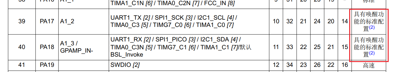
I would like to ask if only those with the note "Standard configuration with wake-up function" support low-power wake-up.  I have checked the "MSPM0 G Series 80MHz Microcontroller Technical Reference Manual" document, and it does not clearly state whether all GPIOs or specific GPIO ports support it.

  • Hi Tony,

    All pins can wake from most low power modes conditions. Waking from SHUTDOWN mode is limited to specific pins; the pins capable of shutdown wake are the open drain, high drive, and Standard with Wake (contains the 2 footnote).

    Regards,
    Luke

  • I would like to consult about the clock issue of mspm0g3107.
    1.  The Datasheet of mspm0g3107 describes that the MCU has an internal oscillator SYSOSC.  Does this mean that there is no need to add an external high-frequency crystal oscillator?  Have other customers used it in this way?
    2.  There are two parameters that can be modified for SYSOSC: factory-modified parameters and user-modified parameters.  How should these two parameters be understood?

  • Hi Tony,

    1. There is an internal oscillator so no external crystal is required. A user may have an external crystal if accuracies higher than our SYSOSC can provide is required. Most use cases will use the internal oscillator only. For CAN communication, it is recommended to have an external crystal due to the accuracy requirements on the CAN BUS.
    2. There is the ability to User Trim the SYSOSC, which can get to 25kHz accuracy. See section 2.3.1.2.4 in the Technical Reference Manual.
      1. The step size for adjustments with ROSC present is 50kHz, which means you can get 25kHz accuracy.
      2. For no ROSC present, the step size is 100kHz so you can get 50kHz accuracy.
      3. Further math proof, for example if you are off by -40kHz of target frequency increase the step (+50kHz) and you will be off by +10kHz.
  • I have another question about the ADC. The datasheet describes that the reference power supply of the ADC can be the VDD of the MCU. If the VDD of the MCU is used as the reference power supply, how should the VREF+/VREF- pins of the MCU be handled? Can they be left floating or used as ordinary GPIO pins?


    Also, does the use of external references mentioned in the reference manual include the case of VDD?

    From an architectural perspective, VDD is independent as a reference.

  • What are the requirements for the input voltage divider resistor? Now, specific recommended values are needed. It would be even better if there were relevant principle explanations.

    Could you please reply to both the previous and current questions at the same time? Thank you!

  • There's another issue. The reference voltage VREF+ of the ADC requires a decoupling capacitor. The capacitance value of this capacitor is not specified. Please also take a look

  • The VDD selection VRSEL = 0, will be all internal connection and requires no external capacitor, so the VREF pins can be used for other functions. The VRSEL = 1 will use the VREF pins for external connection, and VRSEL = 2 will use VREF+ and VSS, a capacitor is required for both external and internal reference.

    If you require very high accuracy I would recommend using the external reference option, you can route VDD into VREF+ so a true external reference is not needed. Alternatively, since the internal reference would connect to the VREF+ node, enabling the internal reference but setting the ADC setting to use external reference will allow the use of VREF- for the ADC ground. The reason is VREF- would be used as an analog ground to help separate any digital switching noise which improves ENOB performance.

  • Do you mean if you were to connect a voltage divider as the input to the ADC channel? I typically do below 10k ohm resistors but it depends on the voltage you're using as you still should not violate the digital IO current specs for the input pin (6mA or 20mA depending on IO type). 

    You do get an RC through the voltage divider and I do recommend creating a low-pass filter to improve your ADC results. If using a voltage divider all you would need is a capacitor to create the filter. Forgive my MS paint drawing, but you would get a low pass filter through R1 and C1.

  • Hi Tony,

    The capacitor is 1uF - see the electrical characteristics for the VREF.

    Regards,
    Luke