AM2432: How is the TX_IPG register used?

Part Number: AM2432
Other Parts Discussed in Thread: TMDS243EVM

Tool/software:

Hello,

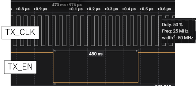
On a custom board using AM2432, I'm experiencing an issue where the 100M Ethernet IPG is set to 480ns.

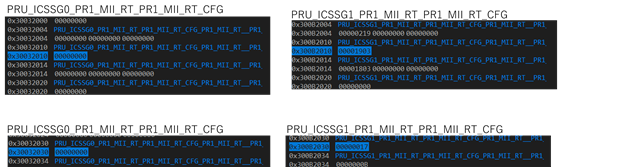
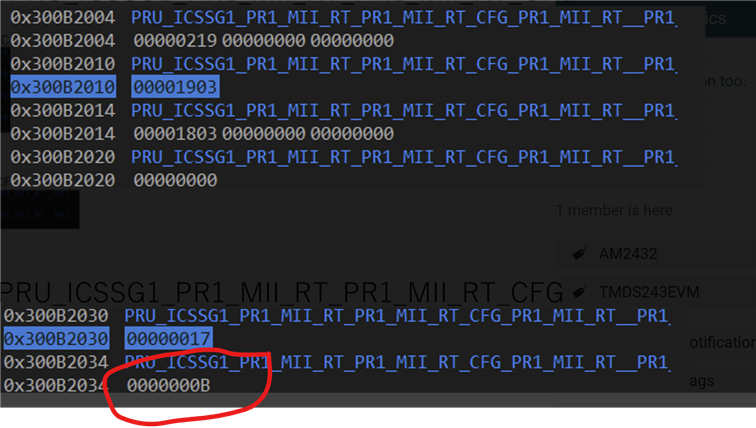
After some research, I found that IPG can be set to 960ns by changing TX_IPG1 register 0x0x30032034 from 0x0B to 0x17, instead of TX_IPG0 register 0x0x30032030.

I would like to analyze why this is happening and whether the cause lies in the firmware, SDK, or hardware,
so could you please tell me which module is using this TX_IPG register to adjust the IPG?

Regards,
Nishimori

  • Hi Nishimori, 

    IPG adjustment occurs during link speed transitions between 100M and 1G Ethernet or vice versa. This is managed by ICSS Ethernet driver.
    The timing calculations are based on different clock frequencies: 100 Mbps MII operates with a 25 MHz clock (40ns per cycle), while 1 Gbps RGMII uses a 125 MHz clock (8ns per cycle). For 100 Mbps MII, achieving a 960ns IPG requires 24 clock cycles (960ns ÷ 40ns), while 1 Gbps RGMII needs 12 clock cycles (96ns ÷ 8ns). Since the register values are set to one less than the actual clock cycle count as it has to transmit on next cycle, this explains the usage 0x17 (23 in decimal) for 100 Mbps and 0xB (11 in decimal) for 1 Gbps operation.

    480ns is not expected. What is the value you are seeing in the register?
    Are you using RTOS or Linux?
    If you are using RTOS, Icssg_updateLinkSpeed100MB() and Icssg_updateLinkSpeed1G() is used to update the link speed.

    Note:
    - if you are programming TX_IPG1 you need to write TX_IPG0 (this is a workaround for a hardware bug, i.e read the TX_IPG0 and write the same value back to TX_IPG0
        Icssg_wr32(hIcssg, baseAddr + CSL_ICSS_G_PR1_MII_RT_PR1_MII_RT_CFG_REGS_BASE + CSL_ICSS_G_PR1_MII_RT_PR1_MII_RT_CFG_TX_IPG1, 0xBU);
        Icssg_wr32(hIcssg, baseAddr + CSL_ICSS_G_PR1_MII_RT_PR1_MII_RT_CFG_REGS_BASE + CSL_ICSS_G_PR1_MII_RT_PR1_MII_RT_CFG_TX_IPG0, 0xBU);

    - Wire clk bit needs to be set.

    BR
    JC

  • Hi,

    480ns is not expected. What is the value you are seeing in the register?

    TX_IPG0 0x30032030 0x17U 
    TX_IPG1 0x30032034 0x0BU  was set.

    Are you using RTOS or Linux?

    I'm using freeRTOS.

    After debugging, I found that Icssg_updateLinkSpeed100MB had been called only once, and Icssg_updateLinkSpeed1G had never been called.

    Icssg_updateLinkSpeed100MB had the argument macPort = ENET_MAC_PORT_FIRST = 0 specified, and I confirmed that 0x17U had been written to the TX_IPG0 register.
    This seemed fine, but when communication began, the IPG was 480 ns.
    I debugged again, and no matter what value I rewrote the TX_IPG0 register to, the IPG did not change.
    I then tried rewriting the TX_IPG1 register, and the IPG changed to the value of TX_IPG1.
    →Setting TX_IPG1 to 0x17 changed the IPG to 960 ns.

    From this, I have determined that the TX_IPG1 register is being referenced, even though this is port 0.
    I would like to know if this is due to a firmware issue or a custom board issue.
    Where is the register value written to TX_IPG0/1 referenced?


    - This issue does not occur in a TMDS243EVM environment configured with almost the same firmware, and TX_IPG0 is referenced correctly.
    - The custom board has two ports, and only port 0 is connected to a LAN cable via 100M Ethernet.
    - SDK: mcu_plus_sdk_am243x_11_00_00_15

  • Hi Nishimori?

    I debugged again, and no matter what value I rewrote the TX_IPG0 register to, the IPG did not change.

    Can you confirm when you read it back the value is 0x17 i.e intact in the memory TX_IPG0?

    BR
    JC

  • Hi,

    Can you confirm when you read it back the value is 0x17 i.e intact in the memory TX_IPG0?

    I checked it in this way

    1. Use the debugger to confirm that 0x17 is written to TX_IPG0.
    2. Overwrite the TX_IPG0 register (0x30032030) with 0x17.
    3. Run → Check the signal and confirm that the IPG remains at 480 ns.
    4. Break and check the TX_IPG0 register → 0x17 is written.

  • Hi,

    2. Overwrite the TX_IPG0 register (0x30032030) with 0x17.

    >> If you are calling this this API Icssg_updateLinkSpeed100MB() then you should not see the issue. If you are manually overwriting TX_IPG1 then you have to follow the order I suggested above (check note section). 

    If it's not solving, 

    Can you probe the TX_CLK of the PHY?

    Which PHY are you using in the custom board?

    BR
    JC

  • Also share TXCFG0/1 register values. 

  • Hi,

    >> If you are calling this this API Icssg_updateLinkSpeed100MB() then you should not see the issue. If you are manually overwriting TX_IPG1 then you have to follow the order I suggested above (check note section). 

    Yes. This API is being called, and as a result, 0x17 is written to TX_IPG0. However, it appears that the actual IPG reference is TX_IPG1.
    I've confirmed that manually writing to TX_IPG1 and then to TX_IPG0 reflects the value in TX_IPG1 and changes the IPG,
    but I'm still curious as to why TX_IPG1 is being referenced in the first place.

    The PHY used is a DP83822l.

    The TX_CLK is 25 MHz, and a waveform diagram is shown below.

    TXCFG0 is 0x00001903 Addr:300B2010
    TXCFG1 is 0x00001803 Addr:300B2014
    For reference, the memory values ​​are pasted directly into the diagram.

    In previous questions and answers, I referred to register 0x30032030 (ICSSG0), but the correct value is register 0x300B2030 (ICSSG1).

  • Hi Nishimori, 

    Thank you for sharing logs. 

    Can you share the schematics?

    I still see 0x0000000B, looks like you have swapped MII pins.

    0x0000000B = 100M = 480ns

    BR
    JC 

  • Hi,

    I've attached the PHY circuit diagram (some parts have been masked).
    Although I haven't used it yet, there is another similar circuit called PHY2.

    ↓PHY2 (unused)

  • I'm curious: Why still 0x0b is written in the TX_IPG register? Can you set both IPG to 0x17 (remember follow the sequence for TX_IPG1 register programming as mentioned above)?

    I've confirmed that manually writing to TX_IPG1 and then to TX_IPG0 reflects the value in TX_IPG1 and changes the IPG,
    but I'm still curious as to why TX_IPG1 is being referenced in the first place.

    this is the hardware bug which I mentioned above.

    I don't see any issue w.r.t schematics above. 

    BR
    JC

  • I'm curious: Why still 0x0b is written in the TX_IPG register? Can you set both IPG to 0x17 (remember follow the sequence for TX_IPG1 register programming as mentioned above)?

    This register diagram shows the register values ​​when using the SDK as is, without any modifications.
    Of course, I can modify the source code and write 0x17 to the TX_IPG0/1 registers.
    Furthermore, I confirmed that following the procedure and writing 0x17 to TX_IPG1 corrects the IPG to 960 ns.
    →The IPG problem itself has been resolved.

    However, as it stands now, Icssg_updateLinkSpeed100MB() is called, setting TX_IPG0 to 0x17 (TX_IPG1 is left unchanged, defaulting to 0x0B).
    I would like to determine the cause of the problem where the actual IPG references the value of TX_IPG1.

    Which module reads the 0x0B written in TX_IPG1 and sets the IPG to 480 ns?
    Is it in the PHY source?

    I don't see any issue w.r.t schematics above. 

    Thank you for checking. I understand that it is unlikely to be a hardware issue.

  • However, as it stands now, Icssg_updateLinkSpeed100MB() is called, setting TX_IPG0 to 0x17 (TX_IPG1 is left unchanged, defaulting to 0x0B).
    I would like to determine the cause of the problem where the actual IPG references the value of TX_IPG1.

    Which module reads the 0x0B written in TX_IPG1 and sets the IPG to 480 ns?
    Is it in the PHY source?

    Looks like in your case PHY link up/down mapping to enet driver is somehow swapped?