This thread has been locked.

If you have a related question, please click the "Ask a related question" button in the top right corner. The newly created question will be automatically linked to this question.

AM2634: Error Frame while MCAN work with CANFD and Classic CAN

Part Number: AM2634
Other Parts Discussed in Thread: SYSCONFIG

Tool/software:

Dear Expert

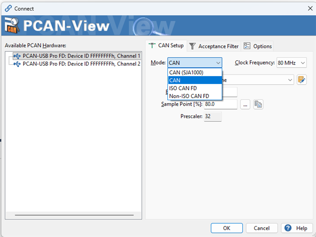
Customer setup a CAN system with 3 nodes connection: one CAN BOX setting as CAN FD, second CAN BOX setting as Classic CAN, and AM2634 MCAN0 setting as some channel in CAN FD with some channel in Classic CAN.

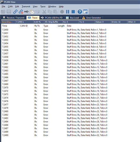
The communication between 3 nodes work well while the AM2634 only send/receive CAN FD message or only send/receive Classic CAN message.  However after enable AM2634 send/receive both CAN FD and Classic CAN, it will happen many error frame.

Customer also test the F280039 to replace AM2634 in the CAN BUS, the communication work well even if F280039 send/receive both CAN FD and Classic CAN.

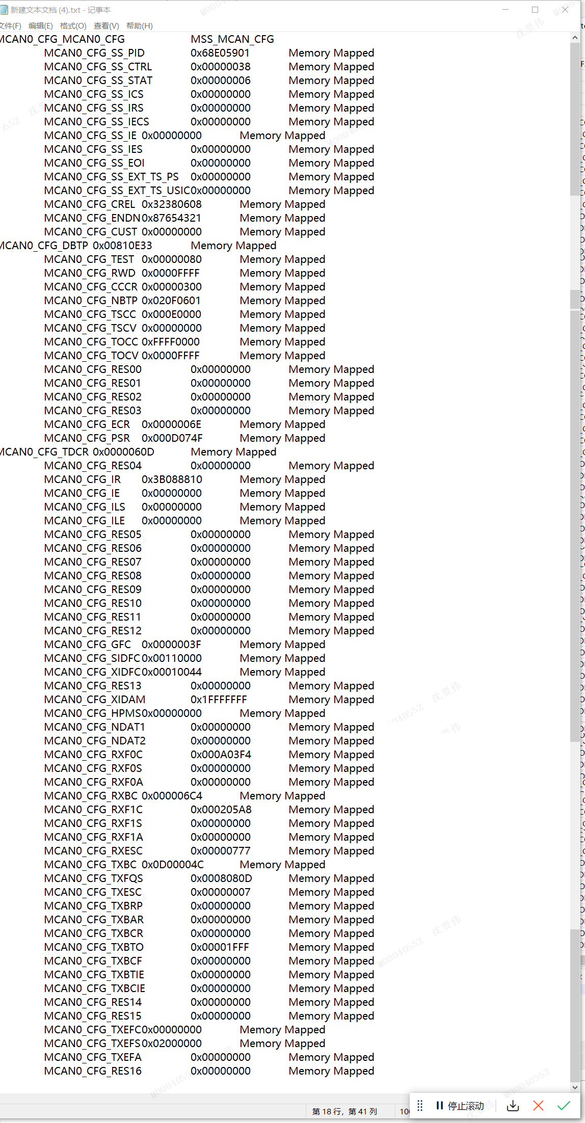
We double check the MCAN all register setting between F280039 and AM2634, there are almost same setting, except the F280039 MCAN clock set as 40Mhz / (7+1) and AM2634 MCAN clock set as 80Mhz / (15+1).

Do we get advice if any other difference between F280039 and AM2634 MCAN module may cause error frame happen only in AM2634?

  • Hi Terry,

    Can you provide additional information on what was changed to "enable AM2634 send/receive both CAN FD and Classic CAN"?
    It sounds like the hardware setup is correct given that it works as expected in a particular mode.

    CAN-FD supports regular CAN messages on the same CAN bus, so your control of CAN-FD vs non CAN-FD should only be applied when configuring the MCAN_TX (transciever) block.

    Can you provide the similar code/configuration that is working for the F280039x device that is working as expected as well as the AM2634 code/configurations?

    Best Regards,

    Zackary Fleenor

  • to enable AM2634 send/receive both CAN FD and Classic CAN, means that some channel configurate message as CAN FD frame, and some other channel configurate message as Classic CAN frame, both two types frame enable transceiver in the CAN BUS.

    Below is configuration code and register value in AM2634, could you please help check if anything need optimization?  

  • Hi Terry,

    It is hard to review the code in the screenshot, can you copy and paste the text into a <CODE> block using the Insert function shown below?

    Can you provide the same mention above with the register dump as well?

    When you say that some channels are configured to CAN-FD and other remain configured to CAN, each MCAN IP supports a single channel and each channel should have an associated MCAN transciever. Can you provide a block diagram of the test setup to better understand how the various MCAN channels are connected to the CAN bus?

    Best Regards,

    Zackary Fleenor

  • Hi Fleenor

    Customer company computer cannot send out the text file so that they only could capture the picture to show register. 

    sorry what I say the channels should be mailbox number, customer configured separate mailbox for CANFD or CAN as below code, this is just part of code and the full configuration code which I also put as attachment in above post.    Please help verify if this usage is ok? 

    Or do we have example firmware to configurate both CAN FD and CLASS CAN in AM2634? Could we make this example to verify the performance


  • Hey Terry,

    Understood, thanks for sharing what you can. I am not aware of an example for this but I will create a ticket with the SDK team for the same.

    I have a few follow up questions to assist in debugging the issue.

    For the CAN-FD function, are the arbitration bit rate and data bit rate the same? If not, what are they?

    What is the data bit rate during CAN function?

    Can you share the equevelent code that is working for the F280039x device?

    During the testing, does the reciever function continue to work as expected? (Other devices can send CAN or CAN-FD messages and AM2634 properly recieves them?)

    Does the order of the protocol switching matter? ie. Will it work when starting in normal CAN mode, then fail when switching to CAN-FD mode, or does it work when starting in CAN-FD mode, then fail when switching to CAN mode?

    Can the device switch back to the original mode and resume proper transmission?

    Thank you for the additional information.

    Best Regards,

    Zackary Fleenor

  • Hi Fleenor

    Please check the AM2634 bit rate setting as below capture, F280039 are almost same setting. The only difference are prescalar value for nom bitrate is 15 on AM2634 and 7 on F280039, prescalar for data bitrate is 1 on AM2634 and 0 on F280039.  

    And below please check the code configuration for F280039.    

    The FD and Claasis frame are send in the CAN BUS by independence sequence without switch logic. Basically classic frame send by a fix period, and FD frame send by more frequency according operation. Both FD and Classic frame could continue send and receive, just sometime will report error frame. AM2634 will report error much frequency while 280039 almost do not report error. 

    Customer would like to double confirm whether MCAN module is exactly same for AM2634 and F280039, because they has already manufacture 60set product and plan release to CAR OEM in next week, they are urgent to get our confirmation if AM2634 need any difference setting by next week.

  • Hi Terry,

    Yes, the fundamental core MCAN IP of both AM2634 and F280039 are the same Bosch IP, there is no difference in the underlying data/register structures and related configuration parameters.

    Is it possible for them to probe the CAN_[H:L] and MCAN_[TX:RX] signals during proper operation and during failing/error-frame operation?

    Best Regards,

    Zackary Fleenor

  • Hi Fleenor

    Could we setup a example for FD and Classic CAN in difference mailbox base on AM2634 to verify if it could work ok without error frame? Maybe it do not need much time because we already have separate example and just need combine it into one MCAN project, baud rate could config same as customer setting.

  • Hey Terry,

    I have limited bandwidth this week to go and check the Classic CAN example, but I have verified that CAN-FD is working as expected without generating an error frame. Is the same CAN TRX IC being used for both MCAN channels, i.e. a designated transceiver for each channel. 

    Instead of switching between Classic CAN and CAN-FD on a single MCAN IP, could you configure a second MCAN IP to operate the CAN-FD mode and dedicate the current MCAN IP to using Classic CAN?

    Best Regards,

    Zackary Fleenor

  • Hi Fleenor

    Yes, the same CAN TRX IC used for both MCAN channels, it is challenge for customer configure second MCAN IP, because the hardware is already fixed and only one CAN TRX IC connect one MCAN IP in the board, so the CAN-FD and Classic CAN frame have to used by one MCAN IP. 

    We capture the waveform as below for error frame moment, bule signal is CAN BUS in TRX IC and red signal is CAN TX pin on AM2634. Please help review if there are any wrong?


  • Hi Terry, Thank you for sharing this. Nothing obvious is sticking out from first glance. What is the control in software to determine whether to use Classic CAN or CAN-FD? When this switch happens, is application taking proper care to reset and reconfigure the entire MCAN IP for alternate mode of operation? 

    Essentially the MCAN_Config and MCAN_Init functions need to be called explicitly for executing each operating mode (Classic CAN, CAN-FD) as well as adhering to the requirement of putting the MCAN IP into SW Initialization mode when making configuration register changes.

    Can you confirm the mechanism used to make the switch and initialization/re-initialization steps taken when the switch occurs?

    Best Regards,

    Zackary Fleenor

  • Hi Terry,

    Another thing I just thought of, due to the different MCAN IP CLKs between the devices (80MHz vs 40MHz), the data timing segment and transmitter delay compensation values should be unique between the F280039x and AM263x configurations. Incorrect values for your CAN-FD timing parameters for the AM263x MCAN would likely lead to this kind of error scenario.

    Can you please double check these with the following app note and associated XLS tool:

    https://www.ti.com/lit/an/sprac35/sprac35.pdf

    http://www.ti.com/lit/zip/sprac35

    Another option would be to update the clock API's and force the AM263x MCAN source clock to 40 MHz.

    Best Regards,

    Zackary Fleenor

  • Hi Fleenor

    Customer software do not reset or reconfigure the MCAN IP, they configure some mailbox as CAN-FD and another mailbox as CAN-Classic in the beginning, then when they want to send CAN-FD or CAN-Classic message, just put message into the correct mailbox buff and start this mailbox. You could check the configuration code in my above post.

    Do you think MCAN IP cannot support customer current usage, and they have to reset and reconfigure the MCAN IP for alternate mode? However customer firmware could run well on F280039, why only happen issue in AM2634?

  • The app note and XLS tools in your link looks for ECAN and DCAN, does it also meet MCAN? 

    Customer configurate the MCAN Timing segment in the sysconfig and pass the sysconfig checking, could you review the setting value in my above post if there are any problem? 

    update clock API and force AM263x MCAN source clock to 40Mhz is a good idea, we also have this though however we do not find the relationship API function, do you know how to implement this?   

  • Hey Terry,

    Yes, the time segment calculations are still applicable regardless of the underlying CAN IP in this case. Changing the Host CLK speed from 40MHz to 80Mhz results in changes to the expected bit timing configuration. The SysConfig implementation here doesn't do any validation of the timing parameters yet, it just generates the code according to the user input. It is up to the user to confirm proper configuration values, but we do plan on improving this in a future release.

    The SOC_rcmSetPeripheralClock() function can be used to control the MCANx source clock. Additional details regarding other RCM (Reset Clocking Manager) controls/functions can be found at the link below.

    https://dev.ti.com/tirex/explore/content/mcu_plus_sdk_am263x_10_02_00_13/docs/api_guide_am263x/group__DRV__SOC__RCM__MODULE.html

    Best Regards,

    Zackary Fleenor

  • Hi Fleenor

    Thanks your advice, we have try modify the MCAN CLOCK to 40Mhz in AM2634, and configure the bit timing parameter exactly same for AM2634 and F280039, however the AM2634 still will report the error frame.

    After more debug, we find the issue maybe relate with FIFO usage,  we do the validation to put below code into main.c while loop routine, then error frame will happen, issue looks caused because call WriteMsgRam to fill FIFO by too much frequency. No matter send by CAN FD or by CAN CLASSIC format, no matter run on customer board or AM2634 EVM board, both will happen error frame once below code continue running on main loop.

    Could you please help review if below code is any wrong? Why "if (TxFs.fifoFull == 0)" in below code do not block fill FIFO too much frequency? And why it will cause error freame?

  • Hey Terry,

    Instead of just checking for fifoFull, the customer could evaluate freeLvl and determine if there is available space in the FIFO to store the full set TX messages.

    Please provide screenshots of the MSG RAM and TX configurations for additional evaluation.

    Best Regards,

    Zackary Fleenor

  • Hi Fleenor

    The above is the fifo configuration for sending. When I keep calling MCAN_vTransmit to send CAN data, error frames will occur. Reducing MCAN_vTransmit will also reduce the number of error frames. Why does sending too much CAN data cause error frames?

    /* Maximum TX Buffer + TX FIFO, combined can be configured is 32 */
    #define APP_MCAN_TX_BUFF_CNT (0U)//0
    #define APP_MCAN_TX_FIFO_CNT (CANTxMailNO+2)// //(0)//(APP_MCAN_STD_ID_FILTER_CNT+APP_MCAN_EXT_ID_FILTER_CNT)//(5U)//5//采用FIFO发送
    /* Maximum TX Event FIFO can be configured is 32 */
    #define APP_MCAN_TX_EVENT_FIFO_CNT (CANTxMailNO+2)

    /* Maximum RX FIFO 0 can be configured is 64 *///采用FIFO 0接收
    #define APP_MCAN_FIFO_0_CNT 10//(APP_MCAN_STD_ID_FILTER_CNT+APP_MCAN_EXT_ID_FILTER_CNT)// (5U)
    /* Maximum RX FIFO 1 can be configured is 64 and
    * rest of the memory is allocated to RX buffer which is again of max size 64 */
    #define APP_MCAN_FIFO_1_CNT (0U)

    static void Drv_McanInitMsgRamConfigParams(MCAN_MsgRAMConfigParams *msgRAMConfigParams)
    {
    int32_t status;

    MCAN_initMsgRamConfigParams(msgRAMConfigParams);

    /* Configure the user required msg ram params */
    msgRAMConfigParams->lss = MCAN_STD_ID_FILTER_CNT;
    msgRAMConfigParams->lse = MCAN_EXT_ID_FILTER_CNT;
    msgRAMConfigParams->txBufCnt = APP_MCAN_TX_BUFF_CNT;
    msgRAMConfigParams->txFIFOCnt = APP_MCAN_TX_FIFO_CNT;

    /* Buffer/FIFO mode is selected */
    msgRAMConfigParams->txBufMode = MCAN_TX_MEM_TYPE_BUF;
    msgRAMConfigParams->txEventFIFOCnt = APP_MCAN_TX_EVENT_FIFO_CNT;
    msgRAMConfigParams->rxFIFO0Cnt = APP_MCAN_FIFO_0_CNT;
    msgRAMConfigParams->rxFIFO1Cnt = APP_MCAN_FIFO_1_CNT;

    /* FIFO blocking mode is selected */
    msgRAMConfigParams->rxFIFO0OpMode = MCAN_RX_FIFO_OPERATION_MODE_BLOCKING;
    msgRAMConfigParams->rxFIFO1OpMode = MCAN_RX_FIFO_OPERATION_MODE_BLOCKING;

    status = MCAN_calcMsgRamParamsStartAddr(msgRAMConfigParams);
    DebugP_assert(status == CSL_PASS);

    return;
    }

    /*******************************************************************************
    ** 函数名称: MCAN_vTransmit
    ** 功能描述:发送CAN数据
    ** 输  入: 数据缓存
    ** 输  出:ture 成功
    ** 最后修改: LINJUNSHENG 2024年01月19日
    *******************************************************************************/
    uint16_t MCAN_vTransmit(const uint8_t* txdata,uint32_t u32Id,uint8_t u8Len)
    {

    MCAN_TxBufElement txMsg;
    uint16_t i = 0U;
    uint16_t txMsg_xtd = 0;
    uint16_t txMsg_fdf = 0;
    uint16_t MailBox = 0;
    /

    for(i = 0;i<CANTxMailNO;i++)
    {
    if(CanTxCfg[i].MsgId == u32Id)
    {
    txMsg_xtd = CanTxCfg[i].txMsg_xtd;//
    txMsg_fdf = CanTxCfg[i].txMsg_fdf;
    MailBox = CanTxCfg[i].MailBox;
    break;
    }
    }

    if(txMsg_xtd == 1)//扩展帧
    {
    txMsg.id = (uint32_t)(u32Id)&0x1fffffff; // Identifier Value.
    txMsg.xtd = 1U; // 29-bit standard identifier.
    }

    else//标准帧
    {
    txMsg.id = ((uint32_t)(u32Id)) << 18U; // Identifier Value.
    txMsg.xtd = 0U; // 11-bit standard identifier.
    }

    txMsg.rtr = 0U; // Transmit data frame.

    txMsg.esi = 0U; // ESI bit in CAN FD format depends only on error
    // passive flag.
    txMsg.dlc = u8Len; // CAN + CAN FD: transmit frame has 0-8 data bytes.
    i if(txMsg_fdf == 1)//CAN FD 格式
    {
    txMsg.brs = 1U; // CAN FD frames transmitted with bit rate
    // switching.
    txMsg.fdf = 1U; // Frame transmitted in CAN FD format.
    }
    else
    {
    txMsg.brs = 0U; // CAN FD frames transmitted without bit rate
    // switching.
    txMsg.fdf = 0U; // Frame transmitted in CAN format.
    }
    txMsg.efc = 1U; // Store Tx events.
    txMsg.mm = 0xAAU; // Message Marker.

    for(i = 0; i < u8Len; i++)
    {
    txMsg.data[i] = txdata[i] & 0xFF;
    }

    MCAN_TxFIFOStatus TxFS;
    MCAN_getTxFIFOQueStatus(gMcanBaseAddr, &TxFS);

    if(TxFS.fifoFull==0)
    {
    //发送采用FIFO
    MCAN_writeMsgRam(gMcanBaseAddr, MCAN_MEM_TYPE_FIFO, TxFS.putIdx, &txMsg);//
    MCAN_txBufAddReq(gMcanBaseAddr, TxFS.putIdx);
    }
    else
    {
    return 0;
    }

    return 1;

    }

  • Hey Terry, Yaowei,

    Since we have followed up offline between Jagadish and I, I will mark this thread as closed. Since the issue had so many different facets, I recommend that we create new dedicated E2E threads for follow up questions.

    Terry, for reference's sake, can you provide a summary of the suggested changes implemented/tested by the customer and their resulting outcome in a follow up reply?

    Best Regards,

    Zackary Fleenor

  • Hi Zack

    Attachment AM2634 MCAN example code run on CC-EVM to transmit both FD and Classic CAN package by sequency. 

    Customer test example code with difference CAN BOX and found below behavior:

    • condition 1, CAN BOX support CAN FD function and enable CAN FD function, communication work well to display both FD and Classic CAN package
    • condition 2,   CAN BOX support CAN FD function but only enable CAN Classic function, CAN tools could not display any package
    • condition 3,  CAN BOX do not support CAN FD function, CAN tools will display error frame in some time

    below capture is condition 2 (left) vs condition 1 (right), do you think if the behavior is normal and could you possible help verify if same behavior in your side?

     https://e2e.ti.com/cfs-file/__key/communityserver-discussions-components-files/908/3225.mcan_5F00_external_5F00_read_5F00_write_5F00_am263x_2D00_cc_5F00_r5fss0_2D00_0_5F00_nortos_5F00_ti_2D00_arm_2D00_clang.7z

  • Hey Terry,

    Unfortunately, I do not have access to the ZCANPRO software tool they are using here, and I can't find any solid documentation to review the functionality of the tool.

    However, based on the conditions provided, this is operating as I would expect.

    If only Classic CAN function is enabled, then CAN-FD formatted packets are ignored. I don't understand why the regular CAN messages are being ignored in this case though. I would need more information on the SW tool and HW CAN Box they are using to provide additional analysis.

    I usually use the PCAN-View software to evaluate CAN Bus data with the "Trace" function provided, but I always use the CAN-FD hardware configuration option and not the Classic CAN configuration option.

    I will check out the results when using Classic CAN only and let you know, but this will be specific to the test environment I have.

    Best Regards,

    Zackary Fleenor

  • Hi Zackary Fleenor,

    I don't understand why the regular CAN messages are being ignored in this case though.

    I understand this and i tested this on our PCAN view tool.

    On my tastings i received only one regular CAN message, and after that no regular CAN messages as well.

    I am suspecting this is because in the code first we are transferring regular CAN followed by CAN-FD messages.

    So, after sending first regular CAN message successfully to other end, error frames are getting generated for CAN-FD messages because tool is set to receive only regular CAN messages. So, after retries, that might create bus off and stops the communication.

    Maybe this is the reason we can't be able to receive regular CAN messages as well.

    --
    Thanks & regards,
    Jagadish.