This thread has been locked.

If you have a related question, please click the "Ask a related question" button in the top right corner. The newly created question will be automatically linked to this question.

MSPM0G3507: UART interrupt fail to start with a certain probability (approximately 1/10 probability)

Part Number: MSPM0G3507

After initializing and enabling the UART interrupt, we printed the following two parameters and found that when the parameters were 0x400 and 0, the UART interrupt could run in normally; When the parameters are 0x400 and 0x400, UART interrupt cannot enter (at this time, reinitialize and enable UART interrupt, print parameters are still 0x400 and 0x400, and UART interrupt still cannot enter).
This problem occurs probabilistically (with a probability of about one in ten).

Uart interrupt invalid:
    0x400 = DL_UART_getEnabledInterrupts( UART_2_INST, DL_UART_MAIN_INTERRUPT_RX );
    0x400 = DL_UART_getEnabledInterruptStatus( UART_2_INST, DL_UART_MAIN_INTERRUPT_RX );

Uart interrupt valid:
    0x400 = DL_UART_getEnabledInterrupts( UART_2_INST, DL_UART_MAIN_INTERRUPT_RX );
    0 = DL_UART_getEnabledInterruptStatus( UART_2_INST, DL_UART_MAIN_INTERRUPT_RX );

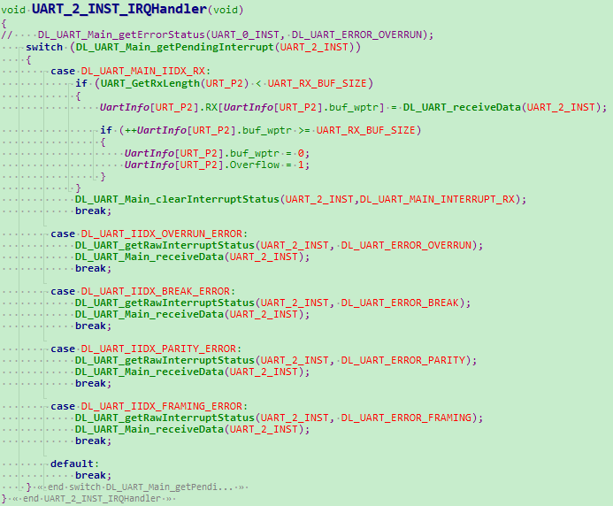
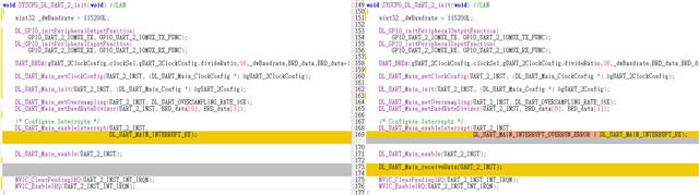
Here is our UART interrupt initialization and interrupt function:

image.png

image.png

image.png

image.png

  • Hi,

    Do you run into any errors?

    -Matthew

  • When the problem occurs, all case options of the Uart_2-INST-IRQHandler interrupt handling function fail to enter (including default).
    The current issue is that the Uart interrupts has a probability of not being able to enter(about 1/10 probability), while other functions appear to be normal (GPIO control/I2C/ADC...)
    What do the return values of function DL_UART_getEnabledInterruptStatus( UART_2_INST, DL_UART_MAIN_INTERRUPT_RX ) with 0x400 and 0 represent respectively?
  • Hi,

    Do you see the same behavior if you try some of the UART example code?

    -Matthew

  • We didn't see the same behavior with the Uart example code.

    We just want to konw:

    1. Why does the return value of function "DL_UART_getEnabledInterruptStatus(UART_2_INST, DL_UART_MAIN_INTERRUPT_RX)" differ from the normal situation when this phenomenon occurs?
    2. When this issue occurs, does the return value of 0 mean that UART interrupt failed to start properly?
    3. Can UART interrupt be reactivated normally when this issue occurs?
  • Where (in your code) do you sample the EnabledInterrupts and EnabledInterruptStatus? Is it in an ISR or in Process-level code?

    At Process level (assuming the UART IRQ is enabled in the NVIC) it's effectively impossible to see this combination, since as soon as it happens the ISR is called and it clears the interrupt.

    The values of the (NVIC) ISPR[0] and ISER[0] might be informative.

    Your ISR seems to accept the "error" interrupts as well; are you enabling those?

    -----

    Unsolicited: I recommend you remove this line from the ISR:

    >DL_UART_Main_clearInterruptStatus(UART_2_INST, DL_UART_MAIN_INTERRUPT_RX);

    Reading the IIDX register already clears that status, so the only effect this can have is to lose a subsequent byte.

  • Hi,

    Let me check on this, and I will get back to you

    -Matthew

  • Thanks, we have removed function "DL_UART_Main_clearInterruptStatus(UART_2_INST, DL_UART_MAIN_INTERRUPT_RX)" in ISR, but the behavior still exist.
    We will not encounter this phenomenon by directly initializing the Uart interrupt and enabling it after powering on the MCU. Only by initializing and enabling it again or enabling the UART interrupt again will this phenomenon occur.
    We are a projector manufacturer, and MCU UART interrupt is enabled when the projector is in standby mode; After the projector is turned on, we will disable the MCU UART interrupt; When the projector returns to standby mode later, it is necessary to re enable the MCU UART, which may result in this phenomenon.

  • Short answer: In your DL_init function, some time before the NVIC_ClearPendingIRQ call, insert something resembling:


    > (void)DL_UART_Main_receiveData(UART_2_INST); // Read and throw away (and clear status)


    Longer answer: I was able to produce your symptom by clearing the UART IRQ while it was Pending. The peripheral (MIS) indicated the Rx interrupt, but the NVIC didn't know about it, and subsequently since the RIS bit was already set the UART didn't issue a new IRQ to the NVIC (aka "stuck").


    TRM (SLAU846C) section 3.3.1.1 (subsection "Setting and Clearing Pending Interrupt Status") appears to describe "Level" behavior for peripheral IRQs, but at least in this case (UART RX) the result seems consistent with "Pulse" behavior -- once the Pending state is cleared, it will not be re-issued.


    You could encounter this case if a byte were being received when you called your DL_init, and completed some time before the ClearPendingIRQ. (The floating point arithmetic probably expands the window here.)


    The usual workaround would be to explicitly clear the RX interrupt bit (RIS) before enabling it. But what I observed was that, while the receiver continued to operate, the RX interrupt still would not be raised (result: the RXDATA quietly overruns). This is presumably because the RXDATA hadn't been read.


    The step that finally cleared things up was to read the RXDATA register (in my case, I used OVRERR to do this). This also has the effect of clearing the RX interrupt bit. So I'm suggesting you just do this arbitrarily when you enable the interrupt.


    This test program contrives to clear every 4th RX interrupt while it's Pending (in the NVIC). Typing into a terminal emulator, every 4th/5th byte is not echoed -- the first because the IRQ was cleared, and the second due to the OVRERR. But the OVRERR code clears the condition, and things go back to normal.

    The .c file:

    /*
     * This started life as the uart_echo_interrupts_standby example
     */
    #include "ti_msp_dl_config.h"
    volatile uint32_t ctr;
    volatile uint8_t gEchoData = 0;
    int main(void)
    {
        SYSCFG_DL_init();
        DL_UART_Main_enableInterrupt(UART_0_INST,
                                  DL_UART_MAIN_INTERRUPT_OVERRUN_ERROR |
                                     DL_UART_MAIN_INTERRUPT_RX);
    
        NVIC_ClearPendingIRQ(UART_0_INST_INT_IRQN);
        NVIC_EnableIRQ(UART_0_INST_INT_IRQN);
        
        while (1) {
            __disable_irq(); // hold it off
            __WFI();
            asm volatile(" nop ");   // Breakpoint here
            ++ctr;
            if ((ctr & 0x03) == 0)
            {
                // Every 4th byte:
                DL_UART_clearInterruptStatus(UART_0_INST, DL_UART_INTERRUPT_RX );
                NVIC_ClearPendingIRQ(UART_0_INST_INT_IRQN);
            }
            __enable_irq(); // let it run
            asm volatile(" nop ");   // Keep the compiler from unrolling
        }
    }
    
    void UART_0_INST_IRQHandler(void)
    {
        asm volatile(" nop "); // breakpoint here
        switch (DL_UART_Main_getPendingInterrupt(UART_0_INST)) {
            case DL_UART_MAIN_IIDX_RX:
                DL_GPIO_togglePins(GPIO_LEDS_PORT,
                    GPIO_LEDS_USER_LED_1_PIN | GPIO_LEDS_USER_TEST_PIN);
                gEchoData = DL_UART_Main_receiveData(UART_0_INST);
                DL_UART_Main_transmitData(UART_0_INST, gEchoData);
                //DL_UART_clearInterruptStatus(UART_0_INST, DL_UART_INTERRUPT_RX );
                break;
            case DL_UART_IIDX_OVERRUN_ERROR:
                gEchoData = DL_UART_Main_receiveData(UART_0_INST);
                break;
            default:
                break;
        }
    }
    

    .syscfg:

    /**
     * These arguments were used when this file was generated. They will be automatically applied on subsequent loads
     * via the GUI or CLI. Run CLI with '--help' for additional information on how to override these arguments.
     * @cliArgs --device "MSPM0G350X" --part "Default" --package "LQFP-64(PM)" --product "mspm0_sdk@2.07.00.06"
     * @v2CliArgs --device "MSPM0G3507" --package "LQFP-64(PM)" --product "mspm0_sdk@2.07.00.06"
     * @versions {"tool":"1.25.0+4268"}
     */
    
    /**
     * Import the modules used in this configuration.
     */
    const GPIO   = scripting.addModule("/ti/driverlib/GPIO", {}, false);
    const GPIO1  = GPIO.addInstance();
    const SYSCTL = scripting.addModule("/ti/driverlib/SYSCTL");
    const UART   = scripting.addModule("/ti/driverlib/UART", {}, false);
    const UART1  = UART.addInstance();
    
    /**
     * Write custom configuration values to the imported modules.
     */
    GPIO1.$name                          = "GPIO_LEDS";
    GPIO1.associatedPins.create(2);
    GPIO1.associatedPins[0].$name        = "USER_LED_1";
    GPIO1.associatedPins[0].assignedPort = "PORTA";
    GPIO1.associatedPins[0].initialValue = "SET";
    GPIO1.associatedPins[0].assignedPin  = "0";
    GPIO1.associatedPins[0].pin.$assign  = "PA0";
    GPIO1.associatedPins[1].$name        = "USER_TEST";
    GPIO1.associatedPins[1].assignedPort = "PORTA";
    GPIO1.associatedPins[1].assignedPin  = "15";
    GPIO1.associatedPins[1].initialValue = "SET";
    
    const Board           = scripting.addModule("/ti/driverlib/Board", {}, false);
    Board.configureUnused = true;
    
    SYSCTL.forceDefaultClkConfig = true;
    SYSCTL.clockTreeEn           = true;
    
    UART1.$name                    = "UART_0";
    UART1.rxFifoThreshold          = "DL_UART_RX_FIFO_LEVEL_ONE_ENTRY";
    UART1.enableDMARX              = false;
    UART1.enableDMATX              = false;
    UART1.targetBaudRate           = 115200;
    UART1.enabledInterrupts        = ["OVERRUN_ERROR","RX"];
    UART1.peripheral.$assign       = "UART0";
    UART1.peripheral.rxPin.$assign = "PA11";
    UART1.peripheral.txPin.$assign = "PA10";
    UART1.txPinConfig.$name        = "ti_driverlib_gpio_GPIOPinGeneric0";
    UART1.rxPinConfig.$name        = "ti_driverlib_gpio_GPIOPinGeneric1";
    
    /**
     * Pinmux solution for unlocked pins/peripherals. This ensures that minor changes to the automatic solver in a future
     * version of the tool will not impact the pinmux you originally saw.  These lines can be completely deleted in order to
     * re-solve from scratch.
     */
    GPIO1.associatedPins[1].pin.$suggestSolution = "PA15";
    Board.peripheral.$suggestSolution            = "DEBUGSS";
    Board.peripheral.swclkPin.$suggestSolution   = "PA20";
    Board.peripheral.swdioPin.$suggestSolution   = "PA19";
    

  • Sorry, we have implemented the countermeasures you provided, but this phenomenon still exists.
    After conducting 200 stress tests, we discovered this issue again.
    The following is a record of the corrections we made based on the solution you provided(They are the initialization and interrupt handling functions of Uart2, with the original writing on the left and modifications made according to your instructions and code on the right). Please help confirm if there are any writing errors or if the countermeasures you mentioned were not imported correctly :

  • Yes, this is the workaround I was suggesting. It sounds as though this reduced the frequency of occurrence; maybe there's more than one way (not shown?) to encounter this condition.

    You should make a point to always read RXDATA for an RX or OVRERR interrupt, even if you throw away the result. My experiments indicated that failing to do this results in a similar (but not identical) condition. I see that both RX and OVRERR have corner cases (buffer overflow?) where RXDATA may not be read.

  • Can I understand it as:
    When the return values of "DL_UART_getEnabledInterrupts( UART_2_INST, DL_UART_MAIN_INTERRUPT_RX )" and "DL_UART_getEnabledInterruptStatus( UART_2_INST, DL_UART_MAIN_INTERRUPT_RX )" are both 0x400, I need to call the "DL_UART_Main_receiveData(UART_2_INST)" function?
    If that's the case, I would write a polling function for judgment and reading, but would this cause any other problems(such as frequent calls to functions "***getEnabledInterrupts***" causing interrupt exceptions or data loss)?

  • When the return values of "DL_UART_getEnabledInterrupts( UART_2_INST, DL_UART_MAIN_INTERRUPT_RX )" and "DL_UART_getEnabledInterruptStatus( UART_2_INST, DL_UART_MAIN_INTERRUPT_RX )" are both 0x400, I call the "DL_UART_Main_receiveData(UART_2_INST)" function, but the both return values still are 0x400, but it seems that the uart interrupt can enter correctly and the problem didn't happen.

    According to our understanding, the return values after calling function "DL_UART_Main_receiveData(UART_2_INST)" should be 0x400 and 0. Why are they still all 0x400?

  • In process-level code (with all interrupts enabled) it is (should be) pretty much impossible to see this combination, since the moment it occurs the ISR is called, which clears the RIS (and thus the MIS) bit.

    In an ISR, or in your re-initialization function (where the UART interrupt is disabled in the NVIC) it would not be surprising to see this combination, since presentation of the interrupt is being held off.

    The fact that (as I understand it) you're seeing this combination in process-level code (with all interrupts enabled) implies that the IRQ to the NVIC has been lost (most likely Clear-ed). I saw one way this could happen in the code you posted, but perhaps something similar is done elsewhere?

    You could, as you describe, poll for the condition as a safety/recovery mechanism (though obviously it would be better to avoid it). The three function calls are quite inexpensive -- each just reads one UART register (IMASK/MIS/RXDATA respectively), and RXDATA is the only one with any side-effects.