AM2432: Flash error after setting to hybrid mode

Part Number: AM2432
Other Parts Discussed in Thread: UNIFLASH, SYSCONFIG

Hi,

I am using AM2432 with the Industrial SDK 11.00.00.08.

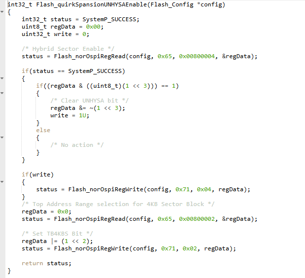
I tried to set my flash (S28HS512T) to hybrid mode following this guide.
It worked the first few times, and I was able to write in hybrid mode on the last 4 KB sectors I had set.
Then, randomly after a power cycle, it seems that the flash no longer responds and it is no longer possible to read or write to it. The last time I ran my program, I started with SBL OSPI and then connected with the debugger to check the execution, but I didn't do anything unusual and I had already run it similarly before without any problems.

Now, if I start with OSPI bootmode and then connect with the debugger, I see that execution stops at 0x418019F0, which seems correct to me because the RBL is probably trying to read the SBL but it cannot read anything from the flash memory.

If I start with DEV bootmode, then do SOC initialization using CCS Scripting, then try to load the sbl_jtag_uniflash example, I get stuck in Flash_open() and the output is:

ERROR: Board_flashOpen:186: FLASH open failed for instance 0 !!!
 [FLASH WRITER] Unable to open FLASH !!!
Some tests have failed!!

What can I do to understand why the flash is no longer responding and figure out what I did wrong following the guide?

Thank you, 

Kind Regards,

Andrea

  • Hi,

    It worked the first few times, and I was able to write in hybrid mode on the last 4 KB sectors I had set.

    Based on the guide, can you tell me which of the configurations you choose? Please refer all the possible combinations of Hybrid mode section and tell me which one you intended to use?

    Regards,

    Vaibhav

  • Hi Vaibhav,

    thank you for your reply.

    I was using this configuration: Top hybrid configuration one thirty-two 4KB sectors and 256KB uniform sectors address map, my code is basically this one you suggest.

    Thank you,

    Kind Regards,

    Andrea

  • Hi,

    So the SBL is at the following offset: 0x0000000. When you map this to our SoC address it would be at 0x60000000 + flash offset = 0x60000000(as flash offset where SBL is present at is 0x0000000).

    So this section will not disturbed at all. And there should be only Block Erase issued for this section of the memory as only SA512 to SA543 comprises of 4 KB sectors.

    So my understanding is that the SBL will still be present if not, then the booting will not happen.

    Please try the following and let me know. Set the bootmode which you are already setting to boot. But do not set the bootmode 9 pin to 1, this is the SFDP pin, leave this to 0 itself.

    Let me know what do you see.

    Thanks,

    Vaibhav

  • Hi Vaibhav,

    thank you for your reply.

    Unfortunately, our custom device only allows us to choose between Dev Mode and OSPI Mode, so I can't act on pin 9. In these two modes, these are the behavours:

    Now, if I start with OSPI bootmode and then connect with the debugger, I see that execution stops at 0x418019F0, which seems correct to me because the RBL is probably trying to read the SBL but it cannot read anything from the flash memory.

    If I start with DEV bootmode, then do SOC initialization using CCS Scripting, then try to load the sbl_jtag_uniflash example, I get stuck in Flash_open() and the output is:

    ERROR: Board_flashOpen:186: FLASH open failed for instance 0 !!!
     [FLASH WRITER] Unable to open FLASH !!!
    Some tests have failed!!

    My concern now is that I may have set some bits in the Flash registers incorrectly during compilation and testing, because I have run many new tests on a second device and have not encountered any problems so far. Is there a way to verify that the flash memory is working correctly by reading its registers? Which registers and bits should I look at, and with what configuration (frequency, multiplier, protocol, other options...)?

    Thank you,

    Kind Regards,

    Andrea

  • Hi Andrea,

    Which registers and bits should I look at, and with what configuration (frequency, multiplier, protocol, other options...)?

    Do you happen to have an external tool with which you can read flash memory? Or the flash Configuration registers?

    If not, then I can suggest something with MCU PLSU SDK path.

    Thanks,

    Vaibhav

  • Hi Vaibhav,

    at the moment I haven't an external tool, can you suggest something?

    Thank you, 

    Andrea

  • at the moment I haven't an external tool, can you suggest something?

    Yes sure, please allow me sometime.

    I can provide you with the steps.

  • Hi,

    Thanks for waiting.

    Suggested Step:

    See the configurations of SBL UART Uniflash by opening the SysConfig. Match the same configuration in SBL JTAG Uniflash and see if the error goes away. If not, then proceed further.

    Further Steps:

    Here are the steps you would need to follow if the above suggestion does not work.

    Try the following way:

    1. How to run the OSPI Flash IO Application?
      1. Download tera term software.
      2. Open the tera term software and open the COM PORT X of UART for AM243.
      3. Set the board in UART Boot mode.
      4. Send the SBL NULL Release HS FS file in the following manner [In order to know if HS FS or GP Images needs to be flashed, please check the device type by reading through this: https://e2e.ti.com/support/processors-group/processors/f/processors-forum/1228618/faq-am6xx-how-to-check-if-device-type-is-hs-se-hs-fs-or-gp ]


        NOTE: If you do not see the SBL NULL Logs on the UART COM Port in one go, you need to send again as this overcomes a errata of warm reset. So basically, send the same SBL NULL Release HS FS file twice one after another(if in one go you do not see the SBL NULL logs on the UART COM Port).

      5. Once, done the cores will be initialized, post which you can then, open CCS and create the AM243.ccxml file from Target Configuration.
      6. Connect to the core in CCS and load the OSPI FLASH IO example.

    Meanwhile you load the OSPI FLASH IO and debug step by step, you would need to read the status and configuration registers, all of them for the flash. So basically registers which start with 0x800.... you would need to read them all, and let me know what are the values of these configuration registers.

    Flash_norOspiRegRead can be used to read the configuration register as well as Status Register values.

    Read these registers inside the function Flash_norOspiOpen, just after readDataCaptureDelay is computed and the flow comes out of the while loop.

    Thanks,

    Vaibhav

  • Hi Vaibhav,

    thank you for your reply.

    I tried it, except I initialized the device with SOC Initialization Script with DEV Mode instead of UART Mode, because our custom device only allows us to choose between DEV Mode and OSPI Mode, and not UART mode.

    Anyway I load OSPI FLASH IO example and tried to read all the status and configuration register, but this is the result:

    This is the code I added:

    diff --git a/mcu_plus_sdk/source/board/flash/ospi/flash_nor_ospi.c b/mcu_plus_sdk/source/board/flash/ospi/flash_nor_ospi.c
    index 6d0ffab9..23062825 100644
    --- a/mcu_plus_sdk/source/board/flash/ospi/flash_nor_ospi.c
    +++ b/mcu_plus_sdk/source/board/flash/ospi/flash_nor_ospi.c
    @@ -1255,6 +1255,41 @@ static int32_t Flash_norOspiOpen(Flash_Config *config, Flash_Params *params)
                 OSPI_setRdDataCaptureDelay(obj->ospiHandle, readDataCapDelay);
                 status = Flash_norOspiReadId(config);
             }
    +
    +        uint8_t regData = 0x00;
    +
    +        status = Flash_norOspiRegRead(config, 0x65, 0x00800000, &regData);
    +        DebugP_log("0x00800000: %x\r\n", regData);
    +        regData = 0x00;
    +
    +        status = Flash_norOspiRegRead(config, 0x65, 0x00800001, &regData);
    +        DebugP_log("0x00800001: %x\r\n", regData);
    +        regData = 0x00;
    +
    +        status = Flash_norOspiRegRead(config, 0x65, 0x00800002, &regData);
    +        DebugP_log("0x00800002: %x\r\n", regData);
    +        regData = 0x00;
    +
    +        status = Flash_norOspiRegRead(config, 0x65, 0x00800003, &regData);
    +        DebugP_log("0x00800003: %x\r\n", regData);
    +        regData = 0x00;
    +
    +        status = Flash_norOspiRegRead(config, 0x65, 0x00800004, &regData);
    +        DebugP_log("0x00800004: %x\r\n", regData);
    +        regData = 0x00;
    +
    +        status = Flash_norOspiRegRead(config, 0x65, 0x00800005, &regData);
    +        DebugP_log("0x00800005: %x\r\n", regData);
    +        regData = 0x00;
    +
    +        status = Flash_norOspiRegRead(config, 0x65, 0x00800006, &regData);
    +        DebugP_log("0x00800006: %x\r\n", regData);
    +        regData = 0x00;
    +
    +        status = Flash_norOspiRegRead(config, 0x65, 0x00800008, &regData);
    +        DebugP_log("0x00800008: %x\r\n", regData);
    +        regData = 0x00;
    +
             /* Enable PHY if attack vector present and PHY mode is enabled */
             obj->phyEnable = FALSE;
             uint32_t phyTuningOffset = Flash_getPhyTuningOffset(config);

    Furthermore, I discovered that the while loop before the code I added is interrupted because readDataCapDelay became 0 and not because the status became SystemP_SUCCESS.

    Do you have any suggestions?
    Thank you,

    Kind Regards,

    Andrea

  • Hello Andrea,

    Furthermore, I discovered that the while loop before the code I added is interrupted because readDataCapDelay became 0 and not because the status became SystemP_SUCCESS.

    So looks like a classic Read ID issue.

    See just before you put the logs we have this while loop inside Flash_norOspiOpen, in which we loop through certain values and figured out which readDataCaptureDelay value can read the flash's device and manufacture id.

    This is done to make sure the OSPI Controller is able to talk to the Flash correctly.

    To understand this in depth, please refer this short FAQ:  [FAQ] AM62x, AM62Px, AM62D-Q1, AM64x, AM275x: Understanding Flash Device ID and Manufacture ID Reads 

    See if this is passed and called correctly.

    Moreover, share with me SysConfig FLASH & OSPI Configurations configured on your setup for the OSPI FLASH IO example. If it is the default setup then you need not share it with me. If it differs then you can share.

    Thanks,

    Vaibhav

  • Moreover, please let me know if you just followed this logic? Or you followed some other logic, please share a snippet of the same.

  • Hi Vaibhav,

    thank you for your reply.

    Moreover, please let me know if you just followed this logic? Or you followed some other logic, please share a snippet of the same.

    In the first device I mentioned in my previous replies, I used the code you indicated above but without checking and setting the write variable (basically just read and write the two registers everytime, but with the same correct values you set). Could this be a problem?

    I ran more tests and it seems that now even the device that appeared to be working correctly now has a similar problem (it doesn't stuck at the same point, but the problem is still with flash access).  In this second device, I directly copied and pasted the code. But now I realized that it should never have worked, because the test if((regData & ((uint8_t)(1 << 3))) == 1) is always false (regData masked with 0x08 never results in 0x01). However, from what I have been able to understand, the erase sector function on 4KB sectors have never failed. Could this have caused the error in the second device?

    Futhermore, I follow the execution of the functions but everytime it reads the Device ID and Manufacture ID I found the value 0x0.

    Moreover, share with me SysConfig FLASH & OSPI Configurations configured on your setup for the OSPI FLASH IO example. If it is the default setup then you need not share it with me. If it differs then you can share.

    The Sysconfig of the projects are the same of the examples.

    Thank you,

    Kind Regards,

    Andrea

  • Hi Andrea,

    In this second device, I directly copied and pasted the code. But now I realized that it should never have worked, because the test if((regData & ((uint8_t)(1 << 3))) == 1) is always false (regData masked with 0x08 never results in 0x01).

    By default the flash drivers are made to work in UNIFORM mode and not HYBRID mode, hence I changed the logic above(in the code snippet) to make sure the flash can be set in Hybrid mode. Therefore the if condition check is modified like that.

    On a newer device, when you run it, you would see that by default the flash will have UNHYSA bit as 0, hence it will not hit the condition, if in any case this bit was 1, then we would have modified it to 0 and written it back to its non-volatile register, to make sure the bit's value is maintained across power cycles/reset of the flash.

    However, from what I have been able to understand, the erase sector function on 4KB sectors have never failed. Could this have caused the error in the second device?

    So by default if hybrid was enabled, 4KB sector erase will definitely not fail. This will not cause any issue as such.

    The Sysconfig of the projects are the same of the examples.

    Thanks for mentioning this.

    Futhermore, I follow the execution of the functions but everytime it reads the Device ID and Manufacture ID I found the value 0x0.

    Please try running the OSPI FLASH DIAG(OSPI Flash Diagnostics) example, it can be found under examples/drivers/ospi

    If you see a success in being able to run the OSPI FLASH DIAG, then it can be sure that the Flash is up and functional.

    I can then suggest you further steps.

    Regards,

    Vaibhav

  • FYI, you can read more about this example here: https://software-dl.ti.com/mcu-plus-sdk/esd/AM243X/latest/exports/docs/api_guide_am243x/EXAMPLES_DRIVERS_OSPI_FLASH_DIAG.html

    Easiest way to run this would be following the steps which I mentioned here, but instead of OSPI FLASH IO, run the OSPI FLASH DIAG:

    • Download tera term software.
    • Open the tera term software and open the COM PORT X of UART for AM243.
    • Set the board in UART Boot mode.
    • Send the SBL NULL Release HS FS file in the following manner [In order to know if HS FS or GP Images needs to be flashed, please check the device type by reading through this: https://e2e.ti.com/support/processors-group/processors/f/processors-forum/1228618/faq-am6xx-how-to-check-if-device-type-is-hs-se-hs-fs-or-gp ]


      NOTE: If you do not see the SBL NULL Logs on the UART COM Port in one go, you need to send again as this overcomes a errata of warm reset. So basically, send the same SBL NULL Release HS FS file twice one after another(if in one go you do not see the SBL NULL logs on the UART COM Port).

    • Once, done the cores will be initialized, post which you can then, open CCS and create the AM243.ccxml file from Target Configuration.
    • Connect to the core in CCS and load the OSPI FLASH IO example.

    I understand that you do not have the UART bootmode option on your DUT.

    You can refer to this piece of code to change the bootmode to UART Bootmode: github.com/.../switch_boot_mode

  • Hi Vaibhav,

    thank you for you reply.

    In this second device, I directly copied and pasted the code. But now I realized that it should never have worked, because the test if((regData & ((uint8_t)(1 << 3))) == 1) is always false (regData masked with 0x08 never results in 0x01).

    By default the flash drivers are made to work in UNIFORM mode and not HYBRID mode, hence I changed the logic above(in the code snippet) to make sure the flash can be set in Hybrid mode. Therefore the if condition check is modified like that.

    Sure, but shouldn't the operation ((regData & ((uint8_t)(1 << 3))) == 1) always be false? regData & 0x8 can never be 0x1, it can be 0x0 or 0x8, so the comparison will always fail. Is that correct, or am I missing something?

    I understand that you do not have the UART bootmode option on your DUT.

    You can refer to this piece of code to change the bootmode to UART Bootmode: github.com/.../switch_boot_mode

    Thank you, I will try it and let you know. There's one thing I don't understand, though: why is it necessary to go into UART Mode? I can still run the demo from DEV Mode with script initialization. Shouldn't it be the same?

    Thank you, 

    Andrea

  • Hello Andrea,

    Sure, but shouldn't the operation ((regData & ((uint8_t)(1 << 3))) == 1) always be false?

    Thanks for bringing this up, I have updated the FAQ. Thank you for pointing this out.

    Is that correct, or am I missing something?

    That's correct.

    Thank you, I will try it and let you know. There's one thing I don't understand, though: why is it necessary to go into UART Mode? I can still run the demo from DEV Mode with script initialization. Shouldn't it be the same?

    Yes you can do so.

    Regards,

    Vaibhav

  • Hello Vaibhav,

    the result seems to be different on the two devices:

    on one, it seems to always read 0xFF every time. While on the second, it manages to read at least the Manufacturer ID and Device ID, but not the expected ones (0x34 and 0x5B1A).

    Thank you,

    Best Regards, 

    Andrea

  • Hi Andrea,

    Lets do the following then. Hopefully this should fix this issue.

    I will provide a code snippet and I will tell you the steps on how you can execute the same.

    Please allow me sometime to send this out.

    Regards,

    Vaibhav

  • Hi Andrea,

    Thanks for waiting.

    So we will try to fix the flash by manually writing to the Non-Volatile Configuration registers.

    I am going to share the code snippet which you would need to write inside Flash_norOspiOpen API.

    Please refer the following code.

    Kind Regards,

    Vaibhav

  • Here is the code snippet:

    static int32_t Flash_norOspiRegWrite(Flash_Config *config, uint8_t cmd, uint32_t addr, uint8_t data)
    {
        int32_t status = SystemP_SUCCESS;
        uint8_t regData = data;
        Flash_DevConfig *devCfg = config->devConfig;
        Flash_NorOspiObject *obj = (Flash_NorOspiObject *)(config->object);
    
        status = Flash_norOspiCmdWrite(config, devCfg->cmdWren, OSPI_CMD_INVALID_ADDR, 0, NULL, 0);
    
        /* Wait a finite interval after WREN */
        // if(status == SystemP_SUCCESS)
        // {
        //    status = Flash_norOspiWaitReady(config, devCfg->flashBusyTimeout);
        // }
        ClockP_sleep(1);
    
        if(status == SystemP_SUCCESS)
        {
            status = Flash_norOspiCmdWrite(config, cmd, addr, obj->numAddrBytes, &regData, 1);
        }
        return status;
    }
    
    static int32_t Flash_norOspiOpen(Flash_Config *config, Flash_Params *params)
    {
        int32_t status = SystemP_SUCCESS;
        Flash_NorOspiObject *obj = (Flash_NorOspiObject *)(config->object);
        Flash_Attrs *attrs = config->attrs;
        int32_t attackVectorStatus = SystemP_FAILURE;
    
        obj->ospiHandle = OSPI_getHandle(attrs->driverInstance);
    
        if(obj->ospiHandle == NULL)
        {
            status = SystemP_FAILURE;
        }
    
        if(SystemP_SUCCESS == status)
        {
            // perform reg write
            obj->numAddrBytes = 3;
            
            Flash_norOspiRegWrite(config, 0x71, 0x0, 0);
            ClockP_sleep(1);
    
            Flash_norOspiRegWrite(config, 0x71, 0x2, 0);
            ClockP_sleep(1);
    
            Flash_norOspiRegWrite(config, 0x71, 0x3, 8);
            ClockP_sleep(1);
    
            Flash_norOspiRegWrite(config, 0x71, 0x4, 8);
            ClockP_sleep(1);
    
            Flash_norOspiRegWrite(config, 0x71, 0x5, 0xA8);
            ClockP_sleep(1);
    
            Flash_norOspiRegWrite(config, 0x71, 0x6, 64);
            ClockP_sleep(1);
    
            uint8_t regData = 0x0;
    
            // /* Set current protocol as 1s1s1s */
            obj->currentProtocol = FLASH_CFG_PROTO_1S_1S_1S;
    
            for(int loop = 0; loop < 7; loop++)
            {
                if(loop == 1){
                    continue;
                }
                regData = 0x0;
                
                status = Flash_norOspiRegRead(config, 0x65, 0x800000 + loop, &regData);
    
                DebugP_log("After Write: Register %u: 0x%x \r\n", (loop + 1), regData);
            }
    
            while(1);
    
            OSPI_configResetPin(obj->ospiHandle, OSPI_RESETPIN_DEDICATED);
            /* Set device size and addressing bytes */
            OSPI_setDeviceSize(obj->ospiHandle, attrs->pageSize, attrs->blockSize);
    
            /* Set command opcode extension type */
            OSPI_setCmdExtType(obj->ospiHandle, config->devConfig->cmdExtType);
    

    After applying the changes, make sure to go to source/board and build libraries with the command

    gmake -s -f makefile.am243x.r5f.ti-arm-clang.freertos PROFILE=debug

    gmake -s -f makefile.am243x.r5f.ti-arm-clang.freertos PROFILE=release

    gmake -s -f makefile.am243x.r5f.ti-arm-clang.nortos PROFILE=debug

    gmake -s -f makefile.am243x.r5f.ti-arm-clang.nortos PROFILE=release

    Once, done, rebuild a basic application like OSPI FLASH IO and start debugging step by step.

    Step inside Board_driversOpen --> ..... -> Flash_open -->...-> Flash_norOspiOpen

    When you reach this function give it a free run until the while(1) loop introduced in the function. Share with me the debug log values printed on the console.

    Looking forward to your response.

    Regards,

    Vaibhav

  • Hello Vaibhav,

    thank you for your reply.

    I tried the code above. On the device that was actually reading values (incorrect, but different from 0xFF), the code worked. I was able to recover the device and reflash it with the SBL null to continue with development.

    However, on the device that always reads 0xFF it seems it didn't work, because the prints still return 0xFF every time. Do you have any ideas for this last device?

    Thank you,

    Best Regards,

    Andrea

  • Hello Andrea,

    I tried the code above. On the device that was actually reading values (incorrect, but different from 0xFF), the code worked. I was able to recover the device and reflash it with the SBL null to continue with development.

    Glad the board has been recovered from FLASH point of view.

    However, on the device that always reads 0xFF it seems it didn't work, because the prints still return 0xFF every time. Do you have any ideas for this last device?

    Considering it is exactly the same flash part as the first device you have and you followed the same steps, if it did not work, we need to try something else.

    Help me by answering these few questions.

    On the second device with the flash which always returns FFh, when did the flash go bad?

    1. Was it like this from the beginning?
    2. Or this happened when you were trying to play around with the UNHYSA bit?

    Looking forward to your response.

    Kind Regards,

    Vaibhav

  • Hi,

    I would suggest if the recovery is not working for the flash, I would have you look at the latest SDK file flash_nor_ospi.c. If the mechanism to recover the flash(which I provided earlier) has not worked for this board, I would have you run the OSPI FLASH Diagnostics example, without any change in the example. If this runs, successfully then that would mean the flash has not gone bad, if this does not run correctly, then the flash has probably gone bad.

    For future Flash debugging, follow the steps here: www.ti.com/.../sprads5.pdf

    Regards,

    Vaibhav