MSPM0G3507: PWM output, initial pulse wider than it should be

Part Number: MSPM0G3507
Other Parts Discussed in Thread: SYSCONFIG

We are using the LP-MSPm0G3507 platform, in standby0 mode, with LFCLK. 

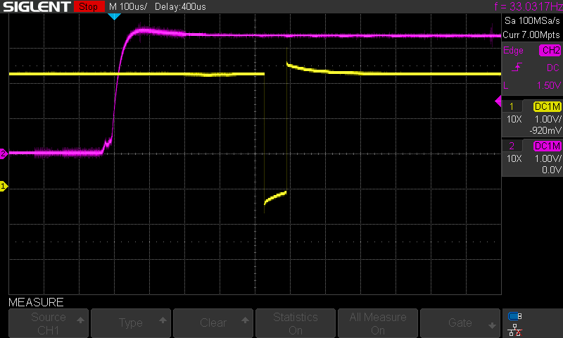
After reboot, and configurations, the initial pulse nominal high output and pulse low is wider, yet we do not understand why.

red trace is nRST, and the yellow trace is the PWM output (which is supposed to be 32uS). Here it is 64uS. The remaining pulses are correct.


Any Ideas? Thanks for Your attention and reply! and Help!

SDS00066.png 

  • using TIMG0, pin 32 of the Launchpad

  • Hi Roger,

    How do you output this pulse (expected 32us)? Do you try to use a PWM function or just toggle GPIO in a interrupt?

    And could you point out which stage in your waveform that MCU is in a standby mode?

  • it is the PWM function.

    the PWM count and trigger is setup in syscfg....

    the below code is after setting up GPIO, SYSCTL, RTC and I2C.

    This is before the WFI in the While..... 

    // 05. PWM init
        SYSCFG_DL_PWM_0_init();
        DL_TimerA_startCounter(PWM_0_INST);
        DL_GPIO_enableOutput(GPIO_PWM_0_C0_PORT, GPIO_PWM_0_C0_PIN);
    Before moving the enable to after the timer was started, we were getting 10s of milliseconds for the initial pulse.
    Any suggestions would be must appreciated.
  • Hi Roger,

    The GPIO enable output should be placed before start counter, to make sure the GPIO is ready for output before counter starts. And also make sure you do not check "Start Timer" in your Sysconfig.

    Besides, which clock do you use as TIMG0 source clock? LFCLK or BUSCLK? Notice that all high frequency clocks except LFCLK will be disabled in Standby0 mode. So you need to use a LFCLK in this case.

    And could you also try whether the pulse width normal if you try to test in debug mode?

  • thank You.

    Yes, using LFCLK. 

    Please elaborate on debug mode versus other... I will be happy to try other modes - such as Free Run??

  • Hi Roger,

    One difference is that MCU may not enter low power mode (standby mode) well in debug mode. For the free run mode, you just need to power on MCU and let MCU run itself without debug access.

    Have you ever try to change the PWM period of the pulse? Is it always 2x relationship between the expected value and measured value?

  • The odd thing is it is only happening for that initial pulse.

    that extra width is a battery consumption issue, even though it is only one pulse.

    i am trying to think of ways to “hide” it. Presuming it is a “startup type of issue, here are my thoughts.

    1) start the timer, with output disabled. Then enable the timer after the pulse would have occurred. ( leading, middle, trailing) makes a difference.

    others?

  • Hi Roger,

    So sorry for late reply.

    What you said could be a workaround. Since the pulse is generated by PWM module and the generation time is predictable。

    As for this issue, are you using a center aligned counting mode or a up or down counting mode?

    Could you share you Load value setting by sysconfig, and the load value when you update counter in your program?

    I suspect maybe the initial load value is different from the reload value. (if you could always see the first pulse is twice of expected time)