TMS570LC4357-EP: MibADC + DMA related issues

Part Number: TMS570LC4357-EP


Dear ti team

When reading data via DMA and writing it to the memory buffer, I encountered the following situation:

During debug execution, data was visible in the buffer, but paused data showed as zero.

I eventually found the forum post I referenced, but still couldn't figure out how to change the cache type to direct-write mode. Later, I disabled the cache and discovered data was present in the buffer.

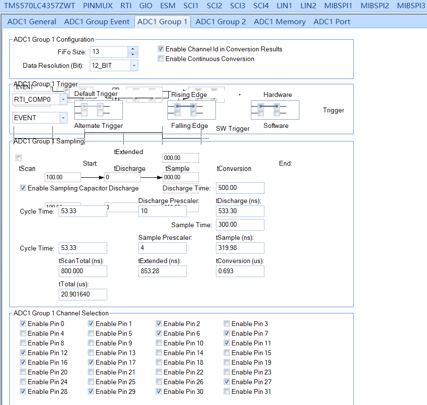
The configuration is as follows:

image.png

1. How do I change the cache type to write through? Will there be any adverse effects after the change?

2. Is the common usage of ADC continuous conversion mode + group memory threshold interrupt or periodic trigger source (RTI/ePWM) +DMA?

3. Is it necessary to collect data 10 times with DMA and average the data of each channel?(Is the data collected in a single session sufficiently accurate?

4. Is there only three threshold interrupts in MibADC1? (Threshold interrupt for each channel is not possible?)

Finally attached is my code, looking forward to reply, thank you.

HL_sys_main.c 

  • Hi Shuo,

    During debug execution, data was visible in the buffer, but paused data showed as zero.
    1. How do I change the cache type to write through? Will there be any adverse effects after the change?

    This is clearly cache-coherance issue.

    Refer below thread once:

    (+) TMDX570LC43HDK: DMA can't read some data correctly(trying to sci tx) - Arm-based microcontrollers forum - Arm-based microcontrollers - TI E2E support forums

    2. Is the common usage of ADC continuous conversion mode + group memory threshold interrupt or periodic trigger source (RTI/ePWM) +DMA?

    Use periodic trigger (RTI or ePWM) + DMA if you need synchronized, deterministic sampling

    Use continuous mode + threshold interrupt, if you don't need synchronization.

    3. Is it necessary to collect data 10 times with DMA and average the data of each channel?(Is the data collected in a single session sufficiently accurate?
    • Start with single samples and measure your noise levels
    • Implement averaging (4-16 samples) if noise is problematic
    • 10 samples is reasonable but not mandatory - optimize based on your requirements
    4. Is there only three threshold interrupts in MibADC1? (Threshold interrupt for each channel is not possible?)

    No, per channel threshold is not available. Only group level threshold is available, i mean we need to assign channels to the group and can provide threshold to the corresponding group.

    --
    Thanks & regards,
    Jagadish.

  • Hi,Gundavarapu,

    Thank you for your reply.

    1. I will attempt to resolve the cache consistency issue using the link you provided.

    2. If I monitor the voltage and current across 25 channels of the Group, driven by RTI, and send a DMA request for 10 data points each time, with the MCU averaging the 10 data points across all 25 channels, is this approach reasonable? Is there an issue with my code? (Please see HL_sys_main.c)

    3. Are you referring to the three threshold interrupts shown in the diagram below when you mention that only group-level thresholds are supported? Are the interrupts for EVENT, Group1, and Group2? I want to use 25 channels for Group1, setting a threshold for each channel. If the value falls below or exceeds that threshold, an action (such as power disconnection) should be triggered.

  • 2. If I monitor the voltage and current across 25 channels of the Group, driven by RTI, and send a DMA request for 10 data points each time, with the MCU averaging the 10 data points across all 25 channels, is this approach reasonable? Is there an issue with my code? (Please see HL_sys_main.c)

    Yes, this approach is generally reasonable. However, make sure this:

    This device has internal FIFO of max 64 words. So, maybe you can keep the 50 words as FIFO for your group. So, after two RTI interrupts the FIFO threshold might reach right, that will trigger the DMA transfer, so DMA will transfer these converted 50 words from FIFO to RAM. Maybe it is not possible to move 10 data points of data in single shot.

    3. Are you referring to the three threshold interrupts shown in the diagram below when you mention that only group-level thresholds are supported? Are the interrupts for EVENT, Group1, and Group2? I want to use 25 channels for Group1, setting a threshold for each channel. If the value falls below or exceeds that threshold, an action (such as power disconnection) should be triggered.

    Not Magnitude threshold interrupt, it is Group threshold interrupt. Refer below section of TRM:

    --
    Thanks & regards,
    Jagadish.

  • Hi,Gundavarapu,

    As shown in the figure, you can see that I used 13 channels, each channel acquired 10 times, and then the average was calculated for each channel. This should be completed within a single RTI interrupt, right? Currently, the program appears to be running normally, and the results match expectations. I'm a bit unclear on your point—if I use 25 channels later, would that exceed the FIFO size?

    Additionally, if the DMA plus average value calculation method is used, there is no need to consider the use of threshold interrupts, so we won't dwell on this issue for now.

  • Hi Shuo Liu,

    Apologies for the delayed response!

    As shown in the figure, you can see that I used 13 channels, each channel acquired 10 times, and then the average was calculated for each channel. This should be completed within a single RTI interrupt, right? Currently, the program appears to be running normally, and the results match expectations. I'm a bit unclear on your point—if I use 25 channels later, would that exceed the FIFO size?

    Your configuration seems to be fine and there is not issue.

    Even with 25 channels also you won't get any issues. Please proceed with this and let me know if you face any issues in future.

    --
    Thanks & regards,
    Jagadish.