


Part Number: MSPM0G3106-Q1
Other Parts Discussed in Thread: MSPM0G3106, UCC33411
Hi Team,
I am trying to interface voltage regulator UCC33411 with MSPM0G3106 MCU and i can see we have 2 input pins from MCU to UCC33411 which are Enable and Fault.
i have configured Enable as Output and Fault as input but when i do this My MCU halts and i can see the voltage at the enable is toggling between 3.3V and 0v And not sure if its because of Fault reaction and the following are the configurations i used,
DL_GPIO_initDigitalOutput(IOMUX_PINCM26);
DL_GPIO_initDigitalInput(IOMUX_PINCM16);
DL_GPIO_initDigitalInputFeatures(IOMUX_PINCM16,DL_GPIO_INVERSION_DISABLE,DL_GPIO_RESISTOR_NONE,DL_GPIO_HYSTERESIS_DISABLE,DL_GPIO_WAKEUP_DISABLE);
DL_GPIO_clearPins(GPIOB, DL_GPIO_PIN_9);
DL_GPIO_enableOutput(GPIOB, DL_GPIO_PIN_9);
DL_GPIO_setPins(GPIOB,DL_GPIO_PIN_9);
this is my config for output and input pin but after configuring this MCU crashes maybe when we suspect some fault triggered by UCC334411 to pull the MCU low. am i missing any peripheral configuration like drive strength, high z or pull up for my MCU?
We have a 27kOhm resistor between EN pin of MCU and Regulator and fault is connected to enable as shown in the snip
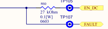
What might be the problem here?
