This thread has been locked.

If you have a related question, please click the "Ask a related question" button in the top right corner. The newly created question will be automatically linked to this question.

MSPM0L1105: MSPM0L1105 : SPI CS PIN in peripheral mode

Part Number: MSPM0L1105
Other Parts Discussed in Thread: SYSCONFIG

Hi TI experts,

I want to use the SPI function of my MSPM0L1105 device in peripheral mode.

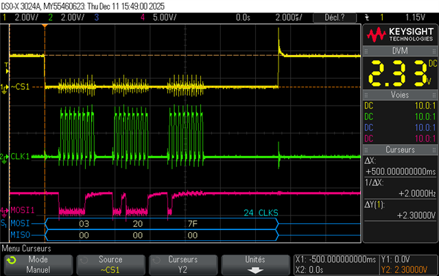
So, the CS pin of the should be an input. But when I check it with the probe of my oscillocsope, it goes to GND. I have a pull-up on this pin (10k) and the voltage falls to 2.4V (the supply is 3.3V).

I have tested to set 3 wires-mode, 4 wires mode, ti-asynchronus mode, with and without pull-up, but it don't works.

I'm sure that it is not a hardware issue on my boars because when I disble the SPI module and set the pin as a GPIO input, the voltage goes to 3.3V....

Any idea ?

thanks for your reply.

BR

  • Hi Michel,

    Can you share your SPI configuration? i.e. pins, SysConfig file

    Can you also share the oscilloscope capture?

    Have you tried using any of the SDK examples for SPI peripheral? There is one called spi_peripheral_echo_interrupts that may be a good reference.

    Best,

    Owen

  • Hi Owen,

    thanks for the answer. Here you have a capture of my scope. As you can see, the CS voltage falls from 3.3V to 2.3V.

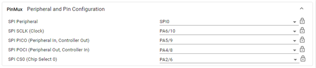
    I can't upload the Sysconfig file, I put a screenshot :

    For the soft, I use the spi_peripheral_echo_interrupts example from the mspm0_sdk_2_08_00_04

    Michel

  • Hi Michel,

    Is this a custom board or an EVM? If custom, can you share the schematic? If EVM, can you share a picture of the board to show connections, etc?

    Can you share what the pinout is for the SPI module? (i.e. expand the Pin Mux drop down)

    Best,

    Owen

  • Hi Owen,

    it's a custom broad. But noting special. I use PA5/PA4 for MOSI/MISO, PA6 for CLK and PA2 for clock.

    BR, 

    Michel

  • Hi Michel,

    Thanks for sharing. I will have to look over this schematic more. If you would like a more in-depth review, please share your schematic with your local sales rep or FAE.

    Also, from the waveform you shared, it looks like there could be a ground issue.

    I would confirm that there are no ground loop or impedance issues, power supply issues, or measurement setup problems with your probe.

    Best,

    Owen

  • Hi Michel,

    I looked over the schematic and noticed that you are missing the bulk capacitor across VDD and VSS. The recommended value is 10uF. You currently only have the 100nF (0.1uF) decoupling capacitor.

    Can you share how you are measuring the waveform? Specifically the setup and test environment.

    Your MOSI line also looks like it is limited to ~2.4V.

    It may be worth also sharing your layout. This should be included with the schematic sent to your local TSR or FAE.

    Have you tried testing the SDK example on an EVM?

    Furthermore, you can also opt to use 3-wire and have a GPIO pin act as CS.

    Best,

    Owen