


Part Number: AM2434
Description:
I am investigating the internal reset circuitry of the AM2434 because I am experiencing unexpected resets when operating an external switching circuit. The device behaves as if it has been reset during this operation.
I am investigating the internal reset circuitry of the AM2434 because I am experiencing unexpected resets when operating an external switching circuit. The device behaves as if it has been reset during this operation.
According to the datasheet (Figure 6-5), RST3 (Power-On Reset) requires an off time of 1200 ns. However, I would like to know if there are other conditions that could cause
MCU_RESETSTATz or RESETSTATz to assert.Observations:
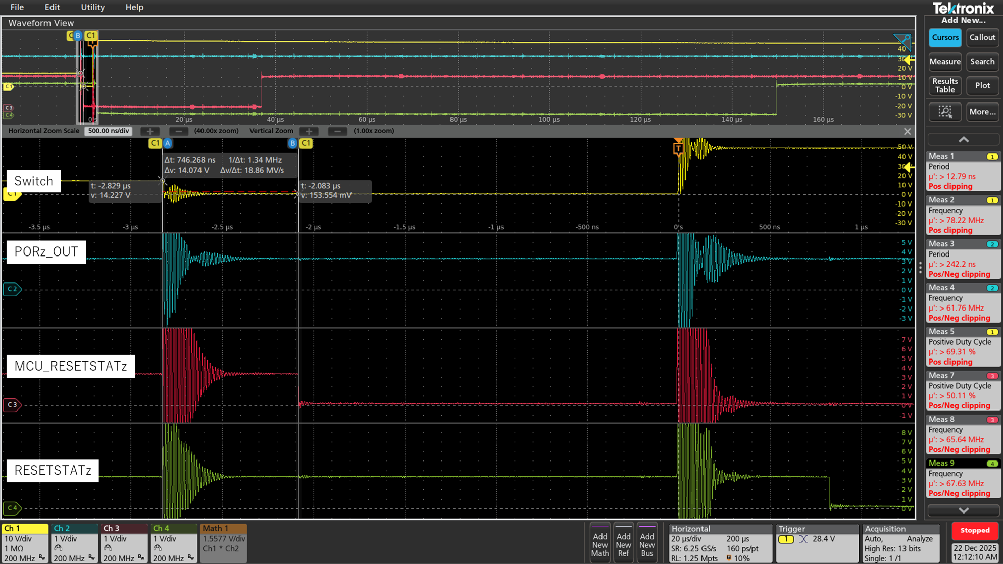
- I monitored
PORz_OUT,MCU_RESETSTATz, andRESETSTATzon the board while the switching circuit was active. - All signals showed noise-like waveforms during switching.
PORz_OUTonly had about 200 ns of noise, butMCU_RESETSTATzandRESETSTATzwent low for the same duration as a normal reset pulse and then returned high.- After this event, when checking the
CTRLMMR_RST_SRCregister in CCS, bit 20 and bit 0 were set.
Questions:
- Besides the 1200 ns requirement for RST3, what other factors could trigger a reset on AM2434?
- What do bits 20 and 0 in
CTRLMMR_RST_SRCspecifically indicate in this context? - Could switching noise on signals or power rails cause warm resets or other reset sources?
 Any guidance or suggestions would be greatly appreciated.


