AM263P4-Q1: 180 second WD timeout on Sitara Am263P4 Custom Hardware in DevBoot Mode

Part Number: AM263P4-Q1
Other Parts Discussed in Thread: AM263P4

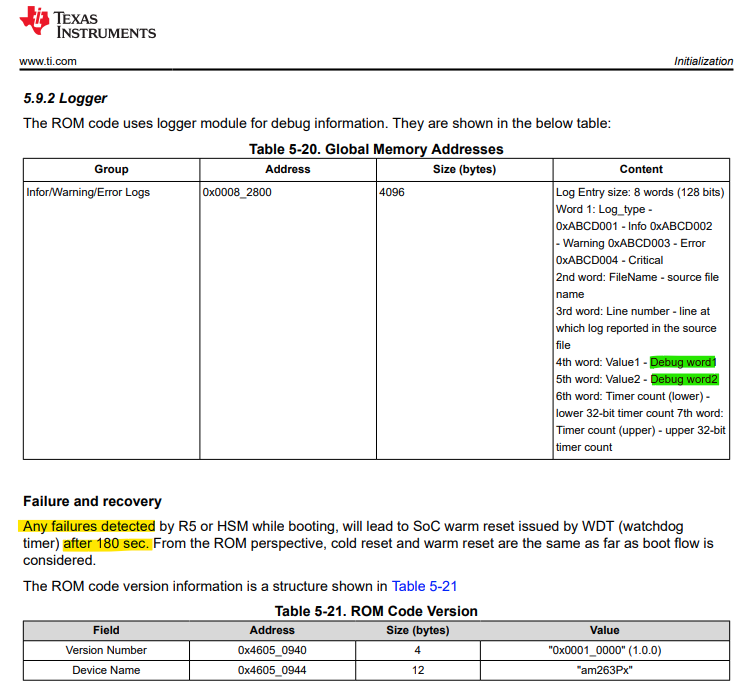
We are currently experiencing an issue where our custom board with the Sitara AM263P4 goes through a reset every 180 seconds when the boot pins are set to DevBoot.  On our board the boot pins are switchable through a jumper.  The boot pins are currently set to DevBoot and we are debugging a main application.  We have found in the technical reference manual a page that states that "Any failures detected... will lead to a warm reset .... after 180 seconds".  We have also found the E2E post linked below that states that if none of the boot image locations has a valid image the "system enters panic mode and resets after 180 seconds" but it seems that this is inteded for non DevBoot modes where a boot image is expected.  

The questions are:

Why does our system reset after 180 seconds when the boot pins are configured for DevBoot mode? 

How do we interpret the "debug words" in section 5.9.2 logger (highligted in green)? 

How do we turn off this 180 second reset when in DevBoot for debugging?

 image.png

 https://e2e.ti.com/support/microcontrollers/arm-based-microcontrollers-group/arm-based-microcontrollers/f/arm-based-microcontrollers-forum/1472201/am263p4-q1-uniflash-cannot-flash-by-xds11s-in-qspi-1s-boot-mode/5661138?tisearch=e2e-sitesearch&keymatch=am263p4%2520180

  • Hi,

    Please note that due to the holiday season, there may be some delay in responses. 

    Kind regards,
    AJ Favela 

  • Hi Theo,

    Can you check if the watchdog is from PMIC ? Just to double confirm.

    Apart from that, can you share the gel loading prints from console? I will be on vaccation from today onwards, response will get delayed

  • The watchdog is not from the PMIC, it happens regardless of PMIC configuration, but our current configuration sets up the PMIC WD to be a 7s open window, 3s close window and 7 failures to reset, but the 180s timeout can happen even if stopped at a brakpoint before the PMIC watchdog is configured.  

    Here is the GEL output: 

    Cortex_R5_0: ***OnTargetConnect() Launched***
    
    Cortex_R5_0: AM263Px Initialization Scripts Launched. 
    Please Wait...
    
    
    Cortex_R5_0: AM263Px_Cryst_Clock_Loss_Status() Launched
    Cortex_R5_0: Crystal Clock present 
    Cortex_R5_0: AM263Px_SOP_Mode() Launched
    Cortex_R5_0: SOP MODE = 0x00000003    
    Cortex_R5_0: OSPI (8S) - Octal Read Mode
    Cortex_R5_0: AM263Px_Read_Device_Type() Launched
    Cortex_R5_0: EFuse Device Type Value = 0x000000AA    
    Cortex_R5_0: AM263Px_dual_or_lockstep_mode() Launched
    Cortex_R5_0: r5fss0 = 0x00000100    
    Cortex_R5_0: r5fss1 = 0x00000100    
    Cortex_R5_0: R5FSS0 is in Lockstep mode 
    Cortex_R5_0: R5FSS1 is in Lockstep mode 
    Cortex_R5_0: MSS_CTRL Control Registers Unlocked
    Cortex_R5_0: MSS_TOP_RCM Control Registers Unlocked
    Cortex_R5_0: MSS_RCM Control Registers Unlocked
    Cortex_R5_0: MSS_IOMUX Control Registers Unlocked
    Cortex_R5_0: TOP_CTRL Control Registers Unlocked
    Cortex_R5_0: *** R5FSS0 DualCore Reset ***
    Cortex_R5_0: *** R5FSS1 DualCore Reset ***
    Cortex_R5_0: R5F ROM Eclipse
    Cortex_R5_0: R5FSS0_0 Released
    Cortex_R5_0: R5FSS0_1 Released
    Cortex_R5_0: R5FSS1_0 Released
    Cortex_R5_0: R5FSS1_1 Released
    Cortex_R5_0: L2 Mem Init Complete
    Cortex_R5_0: MailBox Mem Init Complete
    Cortex_R5_0: r5fss0 = 0x00000001    
    Cortex_R5_0: r5fss1 = 0x00000000    
    Cortex_R5_0: R5FSS0 is in Dual-Core mode 
    Cortex_R5_0: R5FSS1 is in Dual-Core mode 
    Cortex_R5_0: CORE PLL Configuration Complete
    Cortex_R5_0: PER PLL Configuration Complete
    Cortex_R5_0: SYS_CLK DIVBY2
    Cortex_R5_0: DPLL_CORE_HSDIV0_CLKOUT0 selected as CLK source for R5FSS & SYS CLKs
    Cortex_R5_0: CLK Programmed R5F=400MHz and SYS_CLK=200MHz 
    Cortex_R5_0: Configure all Peripheral clocks()
    Cortex_R5_0: 
    
     *** Enabling Peripheral Clocks *** 
    Cortex_R5_0: Enabling RTI[0:3] Clocks 
    Cortex_R5_0: RTI0 Clock Enabled (200MHz)
    Cortex_R5_0: RTI1 Clock Enabled (200MHz)
    Cortex_R5_0: RTI2 Clock Enabled (200MHz)
    Cortex_R5_0: RTI3 Clock Enabled (200MHz)
    Cortex_R5_0: Enabling RTI_WDT[0:3] Clocks 
    Cortex_R5_0: WDT0 Clock Enabled (200MHz)
    Cortex_R5_0: WDT1 Clock Enabled (200MHz)
    Cortex_R5_0: WDT2 Clock Enabled (200MHz)
    Cortex_R5_0: WDT3 Clock Enabled (200MHz)
    Cortex_R5_0: Enabling UART[0:5]/LIN[0:5] Clocks 
    Cortex_R5_0: LIN0_UART0 Clock Enabled (160MHz)
    Cortex_R5_0: LIN1_UART1 Clock Enabled (160MHz)
    Cortex_R5_0: LIN2_UART2 Clock Enabled (160MHz)
    Cortex_R5_0: LIN3_UART3 Clock Enabled (160MHz)
    Cortex_R5_0: LIN4_UART4 Clock Enabled (160MHz)
    Cortex_R5_0: LIN5_UART5 Clock Enabled (160MHz)
    Cortex_R5_0: Enabling OSPI Clocks 
    Cortex_R5_0: OSPI0 Clock Enabled (133MHz)
    Cortex_R5_0: Enabling I2C Clocks 
    Cortex_R5_0: I2C Clock Enabled (48MHz)
    Cortex_R5_0: Enabling TRACE Clocks 
    Cortex_R5_0: Trace Clock Enabled (250MHz)
    Cortex_R5_0: Enabling MCAN[0:3] Clocks 
    Cortex_R5_0: MCAN0 Clock Enabled (80MHz)
    Cortex_R5_0: MCAN1 Clock Enabled (80MHz)
    Cortex_R5_0: MCAN2 Clock Enabled (80MHz)
    Cortex_R5_0: MCAN3 Clock Enabled (80MHz)
    Cortex_R5_0: Enabling MMCSD Clocks 
    Cortex_R5_0: MMCSD Clock Enabled (48MHz)
    Cortex_R5_0: Enabling MCSPI[0:4] Clocks 
    Cortex_R5_0: MCSPI0 Clock Enabled (48MHz)
    Cortex_R5_0: MCSPI1 Clock Enabled (48MHz)
    Cortex_R5_0: MCSPI2 Clock Enabled (48MHz)
    Cortex_R5_0: MCSPI3 Clock Enabled (48MHz)
    Cortex_R5_0: MCSPI4 Clock Enabled (48MHz)
    Cortex_R5_0: Enabling CONTROLSS Clocks 
    Cortex_R5_0: CONTROLSS Clock Enabled (400MHz)
    Cortex_R5_0: Enabling CPTS Clocks 
    Cortex_R5_0: CPTS Clock Enabled (250MHz)
    Cortex_R5_0: Enabling RGMI[5,50,250] Clocks 
    Cortex_R5_0: RGMII5 Clock Enabled (5MHz)
    Cortex_R5_0: RGMII50 Clock Enabled (50MHz)
    Cortex_R5_0: RGMII250 Clock Enabled (250MHz)
    Cortex_R5_0: Enabling XTAL_TEMPSENSE_32K Clocks 
    Cortex_R5_0: TEMPSENSE Clock Enabled (32KHz)
    Cortex_R5_0: Enabling XTAL_MMC_32K Clocks 
    Cortex_R5_0: XTAL_MMC Clock Enabled (32KHz)
    Cortex_R5_0: 
    
     ***All IP Clocks are Enabled*** 
    
    Cortex_R5_0: CPU reset (soft reset) has been issued through GEL on program load.
    Cortex_R5_2: CPU reset (soft reset) has been issued through GEL on program load.
    Cortex_R5_3: CPU reset (soft reset) has been issued through GEL on program load.
    

  • Hi Theo,

    As you said that your board is in DEV boot mode, but from the logs of the GEL script, you can see that it is in OSPI 8s boot mode.

    Cortex_R5_0: SOP MODE = 0x00000003
    Cortex_R5_0: OSPI (8S) - Octal Read Mode
    Cortex_R5_0: AM263Px_Read_Device_Type() Launched

    You might need to recheck the SOP Pins, and configure it correctly into dev boot mode.