This thread has been locked.

If you have a related question, please click the "Ask a related question" button in the top right corner. The newly created question will be automatically linked to this question.

AM2431: For MCSPI peripheral with DMA, how to transfer more than 4096 bytes

Part Number: AM2431
Other Parts Discussed in Thread: AM2432, SYSCONFIG

Hi Experts,

We intend to use MCSPI as a slave device, capable of receiving 16K data sent by the host at once via DMA. 

We testing reveals that if the host sends not more than 4096 bytes, the slave can receive the data correctly. 

However, if the host sends a large amount of data at once, such as 16K, the data received via DMA is abnormal: the memory receives 16K data, but only the last 4K is correct, and the rest is erroneous. The slave receives four copies of the last 4K bytes content. 

For example, if the host sends u32*4KByte data from 1 to 4096, the u32 data received in the slave's memory is not 1 to 4096, but four sets of 3073 to 4096,  the first byte in receives buffer is not 1, but 3073. We would like to know whether this is a bug in the SDK or a limitation of the DMA hardware. 

According to the DMA configuration, it should be able to receive up to 16 bytes * 2048 of data. 

1.png

  • Hello,

    I am not sure on which SDK version you are testing the application on. I would recommend using the latest one. Here it is: https://www.ti.com/tool/download/MCU-PLUS-SDK-AM243X/11.02.00.24

    The reason being I found few commits which might help resolve your issue with DMA.

    Here you go:

    1. https://github.com/TexasInstruments/mcupsdk-core/commit/4d768588852b0bc90a30a45b6355260c443eff05#diff-57541bc9ca53109e199e08e3071a8375f7a64f5f256605dd7b84c8388baacd21

    2. https://github.com/TexasInstruments/mcupsdk-core/commit/1c562a26b166792e3e7f1ac5bb4b4a19430aeab7

    There are other changes as well with are aimed towards improving the MCSPI driver as a whole.

    Also recommended to read this GUIDE, if you have not already: e2e.ti.com/.../faq-sk-am64b-mcspi-integration-guide

    Regards,

    Vaibhav

  • Hi Vaibhav,

    Thank you for your quick response.

    Your response is very helpful for our current design.

    For our application, our AM2432 is SPI slave device, for our customer's SPI data frame length is NOT fixed, so could you please provide the deisgn reference?

    We'd like to use SPI slave DMA for the application.

    Thanks

    Kelven 

  • We'd like to use SPI slave DMA for the application.

    Please refer this

  • Hi Caibhav,

    The data error when length > 4096 bytes is due to a bug on the SPI Master. But there is still some issues with the AM243X MCSPI SLAVE.

    The upper example is not valid for variable length transfer.
    When the slave does not know the length of the next SPI transfer, we can only assume the SPI master will send the maximum data length, such as 16 KB. Therefore, we need calling the MCSPI_Transfer() function with the length set to 16 KB. If the host only sends 5,000 bytes in a particular communication, the DMA completion interrupt will not be triggered. This leads to two issues:

    1. When the communication finishes, only 4,992 bytes of data are refreshed into memory. The remaining 8 bytes can only be refreshed by actively calling the Udma_chDisable() function. Is there a more suitable method to refresh the data and confirm the actual received data length?

    2. Although the actual SPI communication is complete, the DMA interrupt remains pending (because the slave did not receive the full 16 KB of data). How can we actively terminate this communication and prepare for the next one? Directly calling MCSPI_Transfer() at this point will trigger an assertion.

    SDK Version is 11.02.00.24.

  • Hi Liang,

    I am reviewing this and will get back to you in sometime.

    Thanks,

    Vaibhav

  • Hello Liang,

    For variable number of bytes of transfer, this is currently not possible as per the current Software Offering.

    Regarding the issue with 4096 bytes, I would recommend you to have a look at the following E2E which should not take more than 5 minutes of time:  RE: MCU-PLUS-SDK-AM243X: SPI DMA fail when transfer large size 

    Regards,

    Vaibhav

  • Regarding the issue with 4096 bytes, I would recommend you to have a look at the following E2E which should not take more than 5 minutes of time:  RE: MCU-PLUS-SDK-AM243X: SPI DMA fail when transfer large size 

    Hi Vaibhav, Thanks. This topic was also post by me. So the SPI BUG hasn't fixed yet? Perhaps you can refer to the approach of the network module by using chained DMA. We tried it and it can solve the problem to some extent.

  • Hi Liang,

    I see that the other thread was raised by you. Thanks for pointing this out.

    Also if not already conveyed, this is the latest discussion over email.

    Anil mentioned the following:

    In scenarios where the data length is variable, the recommended and correct approach is to use the length information provided by the SPI master device. Typically, this is handled as follows:

    1. The SPI Controller (Master)  first sends a command or header that includes the data length (for example, a length field in the protocol).
    2. The Peripheral(Slave)  receives this header using CPU-based transfer .
    3. Once the length information is decoded, the DMA transfer count is configured with this value.
    4. McSPI DMA is then enabled to read exactly the specified number of bytes.


    If the SPI protocol does not provide the length information upfront, DMA cannot be directly used for the entire transfer. In such cases, interrupt/polling mode must be considered.

    On the DMA Transfer size front, I will confirm from another expert and let you know within sometime.

    Best Regards,

    Vaibhav

  • Hi Vaibhav,

    We have tried using interrupts and found that at the required SPI frequency (25 MHz), interrupt usage leads to receive overflow. That is, the interrupts cannot retrieve the data in the SPI FIFO quickly enough.

    OK, looking forward to your update.

    On the DMA Transfer size front, I will confirm from another expert and let you know within sometime.
  • Hi Liang,

    Found an errata around BCDMA which is a good to know: https://www.ti.com/lit/er/sprz457j/sprz457j.pdf#page=38
    Please refer I2431.

    Could you also check a basic setup like Cache Writeback/Invalidation being performed in your test code?

    Regards,

    Vaibhav

  • Hi Vaibhav,

    We did notice this issue, but It seems to be referring only to BCDMA and does not include the PKTDMA we are using.

    We have resolved the ASSERT issue by proactively additional calls the CSL_pktdmaSetTxRT, and now can send and receive variable length using DMA.

  • Hi Liang,

    We have resolved the ASSERT issue by proactively additional calls the CSL_pktdmaSetTxRT, and now can send and receive variable length using DMA.

    But this still does not answer your query of maximum number of BYTES in one transaction right? 

    Or this fixes your issue. Please help clarify the same.

    Thanks,

    Vaibhav

  • Yes, it fixed the issue. Initially, we could only transfer a maximum of 2048 bytes of data per DMA channel, so we considered referencing the NETWORK module's approach of linking multiple DMA channels. However, it was later discovered that this was unnecessary. Currently, we use a single DMA channel and have achieved the required functionality.

  • Hi Liang,

    Thank you for the confirmation.

    Regards,

    Vaibhav

  • Hi Liang,

    If it does not require much effort, is it possible for you to create a patch of the changes you did to incorporate more than 2048 bytes as you mentioned?

    If the changes are at application level/NDA, it is fine.

    Thanks,

    Vaibhav

  • Hi Vaibhav,

    Firstly, thank you for your great support.

    We will share the source code, please help to double review the source code.

    Liang will share it later.

    Thanks

    Kelven

  • Hello,

    Looking forward to the source code.

    Thanks,

    Vaibhav

  • Hi Vaibhav,

    We directly modified the application code. The original code contained numerous intermediate debugging sections that have not yet been organized, so I extracted the key code. Please kindly help review whether there are any issues with our implementation.

    The key strategy is as follows:
    We added an SPI CS rising edge interrupt. After starting the DMA transmit/receive, if we receive a CS interrupt instead of an SPI completion interrupt, we reset the DMA and retrieve the length of the data already received through the following function deInitMcspiSlaveDMACh().


    extern MCSPI_ChConfig       *gConfigMcspiChCfg[];
    int32_t myUdmaDeInitCh(Udma_ChHandle chHandle,
                                      uint32_t  isChEnabled);


    void terminateMcspiSlaveDMA()
    {
        int32_t                retVal;
        uint32_t index = 2;
        uint32_t chCnt = 0;
        uint64_t               pDesc;
        MCSPILLD_Handle        hMcspi;
        MCSPILLD_InitHandle    hMcspiInit;
        MCSPI_Config *config = NULL;
        MCSPI_Object *obj    = NULL;
        uint32_t               chNum, effByteCnt, peerData;
        MCSPI_UdmaChConfig    *dmaChConfig;
        MCSPI_Transaction     *transaction;
        CSL_UdmapCppi5HMPD    *pHpd;
        MCSPI_ChObject        *chObj;
        uint32_t               baseAddr, irqStatus = 0U;
        Udma_ChHandle          rxChHandle, txChHandle;
        int32_t                status = MCSPI_STATUS_SUCCESS;
        uint8_t *pRxHpdMem, *pTxHpdMem;
        MCSPI_ChConfig      *chConfig;
    
        config = &gMcspiConfig[index];
        obj = config->object;
        hMcspi = obj->mcspiLldHandle;
        hMcspiInit   = hMcspi->hMcspiInit;
        baseAddr     = hMcspi->baseAddr;
        transaction  = &hMcspi->transaction;
        chNum        = transaction->channel;
        chObj        = &hMcspi->hMcspiInit->chObj[chNum];
        dmaChConfig  = (MCSPI_UdmaChConfig *)chObj->dmaChCfg;
        rxChHandle   = dmaChConfig->rxChHandle;
        txChHandle   = dmaChConfig->txChHandle;
        effByteCnt   = transaction->count << chObj->bufWidthShift;
        pRxHpdMem    = dmaChConfig->rxHpdMem;
        pTxHpdMem    = dmaChConfig->txHpdMem;
        chConfig    = gConfigMcspiChCfg[index];
    
        hMcspi->transaction.count = 0;
    
    
    	pHpd = (CSL_UdmapCppi5HMPD *)((uint8_t *) pTxHpdMem + i * sizeof(CSL_UdmapCppi5HMPD));
    	CacheP_inv(pHpd, dmaChConfig->hpdMemSize, CacheP_TYPE_ALLD);
    
    	pHpd = (CSL_UdmapCppi5HMPD *)((uint8_t *) pRxHpdMem + i * sizeof(CSL_UdmapCppi5HMPD));
    	CacheP_inv(pHpd, dmaChConfig->hpdMemSize, CacheP_TYPE_ALLD);
    
    	retVal = Udma_ringDequeueRaw(Udma_chGetCqRingHandle(txChHandle), &pDesc);
    	if (retVal < 0)
    		retVal = Udma_ringFlushRaw(Udma_chGetFqRingHandle(txChHandle), &pDesc);
    
    	retVal = Udma_ringDequeueRaw(Udma_chGetCqRingHandle(rxChHandle), &pDesc);
    	if (retVal < 0)
    		retVal = Udma_ringFlushRaw(Udma_chGetFqRingHandle(rxChHandle), &pDesc);
    	else
    	{
    		pHpd   = (CSL_UdmapCppi5HMPD *)(uintptr_t)pDesc;
    		if (retVal == UDMA_SOK)
    		{
    			status = MCSPI_TRANSFER_COMPLETED;
    		}
    		else
    		{
    			status = MCSPI_TRANSFER_FAILED;
    			//hMcspi->hMcspiInit->errorCallbackFxn(hMcspi, status);
    		}
    
    		if ((status == MCSPI_TRANSFER_COMPLETED) &&
    			(MCSPI_TR_MODE_TX_ONLY != chObj->chCfg->trMode))
    		{
    			if(dmaChConfig->isCqRingMem != UDMA_COMP_QUEUE_RING_MEM_ENABLED){
    				retVal = Udma_getPeerData(rxChHandle, &peerData);
    				DebugP_assert(retVal == UDMA_SOK);
    	//            startTicks = hMcspiInit->clockP_get();
    	//                    while ((effByteCnt != peerData) && (elapsedTicks < transaction->timeout))
    	//                    {
    	//                        retVal += Udma_getPeerData(rxChHandle, &peerData);
    	//                        elapsedTicks = hMcspiInit->clockP_get() - startTicks;
    	//                    };
    				/* Clear Data */
    				retVal += Udma_clearPeerData(rxChHandle, peerData);
    			}
    			DebugP_assert(retVal == UDMA_SOK);
    
    
    			/* Get Byte count received */
    			effByteCnt = (pHpd->descInfo & CSL_UDMAP_CPPI5_PD_DESCINFO_PKTLEN_MASK) >> CSL_UDMAP_CPPI5_PD_DESCINFO_PKTLEN_SHIFT;
    			hMcspi->transaction.count += (effByteCnt >> chObj->bufWidthShift);
    		}
    	}
    
    
        /* Stop MCSPI Channel */
        MCSPI_lld_dmaStop(hMcspi, chObj, chNum);
        hMcspi->state = MCSPI_STATE_READY;
    
        irqStatus = CSL_REG32_RD(baseAddr + CSL_MCSPI_IRQSTATUS);
        if ((irqStatus & ((uint32_t)CSL_MCSPI_IRQSTATUS_RX0_OVERFLOW_MASK)) != 0U)
        {
          retVal = MCSPI_TRANSFER_CANCELLED;
          hMcspi->errorFlag |= MCSPI_ERROR_RX_OVERFLOW;
        }
    
        if (((irqStatus & ((uint32_t)CSL_MCSPI_IRQSTATUS_TX0_UNDERFLOW_MASK << (4U * chNum))) != 0U) &&
          ((hMcspiInit->msMode == MCSPI_MS_MODE_PERIPHERAL)))
        {
          retVal = MCSPI_TRANSFER_CANCELLED;
          hMcspi->errorFlag |= MCSPI_ERROR_TX_UNDERFLOW;
        }
    
        if(hMcspi->errorFlag != 0U)
        {
          hMcspi->hMcspiInit->errorCallbackFxn(hMcspi, retVal);
        }
        else
        {
          hMcspi->hMcspiInit->transferCallbackFxn(hMcspi, MCSPI_TRANSFER_COMPLETED);
        }
    
    }
    
    
    //disable DMA Channel
    int32_t myUdmaDeInitCh(Udma_ChHandle chHandle,
                                      uint32_t  isChEnabled)
    {
        int32_t udmaStatus = UDMA_SOK;
        int32_t status = MCSPI_STATUS_SUCCESS;
    
        if(isChEnabled == MCSPI_UDMA_CHANNEL_ENABLE)
        {
            /* Disable Channel */
            udmaStatus = Udma_chDisable(chHandle, UDMA_DEFAULT_CH_DISABLE_TIMEOUT);
            DebugP_assert(UDMA_SOK == udmaStatus);
        }
    
        if(udmaStatus == UDMA_SOK)
        {
            status = MCSPI_STATUS_SUCCESS;
        }
        else
        {
            status = MCSPI_STATUS_FAILURE;
        }
    
    
        return status;
    }
    
    //disable DMA Channel TX
    int32_t myUdmaDeInitChTX(Udma_ChHandle chHandle,
                                      uint32_t  isChEnabled)
    {
        Udma_DrvHandleInt   drvHandle;
        CSL_PktdmaRT        pktdmaRtStatus;
        Udma_ChHandleInt    chHandleInt = (Udma_ChHandleInt) chHandle;
    
        drvHandle = chHandleInt->drvHandle;
    
        /*
         *  TRT_CTL Bit31 TX_ENABLE
         *  This field enables or disables the channel. Disabling a channel
            halts operation on the channel after the current block transfer is
            completed. Disabling a channel in the middle of a packet transfer
            may result in underflow conditions in the attached application block
            and data loss. When a channel is disabled, the implementation may
            choose to reset all state for the channel. The pause bit should
            be asserted instead of clearing enable directly if the intent is to
            temporarily pause the channel. This field is encoded as follows: 0 =
            channel is disabled 1 = channel is enabled This field will be cleared
            by HW after a teardown is requested to indicate that the channel
            teardown is complete.
         * */
        pktdmaRtStatus.enable   = FALSE;
        pktdmaRtStatus.teardown = FALSE;
        pktdmaRtStatus.forcedTeardown = FALSE;
    
        (void) CSL_pktdmaSetTxRT(&drvHandle->pktdmaRegs, chHandleInt->txChNum, &pktdmaRtStatus);
    
        return UDMA_SOK;
    }
    
    int32_t deInitMcspiSlaveDMACh()
    {
        int32_t              status = SystemP_SUCCESS;
        uint32_t index = 2;
        MCSPI_ChConfig      *chConfig;
        MCSPI_Config        *config = NULL;
        MCSPI_Object        *obj    = NULL;
        MCSPILLD_Handle      mcspiLldHandle;
        uint32_t chCnt = 0;
        MCSPI_ChObject      *chObj;
        MCSPI_UdmaChConfig  *dmaChConfig;
    
        config = &gMcspiConfig[index];
        obj = config->object;
        mcspiLldHandle                = obj->mcspiLldHandle;
    
        chConfig    = gConfigMcspiChCfg[index];
    
        chObj            = &mcspiLldHandle->hMcspiInit->chObj[chCnt];
        dmaChConfig      = (MCSPI_UdmaChConfig *)chObj->dmaChCfg;
    
        myUdmaDeInitCh(dmaChConfig->rxChHandle, dmaChConfig->isChEnabled);
    
        myUdmaDeInitChTX(dmaChConfig->txChHandle, dmaChConfig->isChEnabled);
    
        terminateMcspiSlaveDMA();
    
        return status;
    }


  • Hi Liang,

    I will review this and get back to you in sometime.

    Could you also share the example.syscfg file for me to look at the MCSPI Configuration. It would be okay to share a screenshot of that section itself instead of the entire file.

    Thanks,

    Vaibhav

  • Hi Vaibhav,

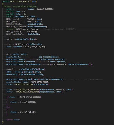
    As show below, MCSPI is configured in polling mode in SYSCFG, and then the following function is actively called in the main function to initialize the DMA.

  • Upon reviewing, it looks good.

    We added an SPI CS rising edge interrupt. After starting the DMA transmit/receive, if we receive a CS interrupt instead of an SPI completion interrupt, we reset the DMA and retrieve the length of the data already received through the following function deInitMcspiSlaveDMACh().

    Is there a possibility of the SPI CS Rising Edge Interrupt and DMA Completion Interrupt at the same time?

  • During the call to transfer, we set a large data length, making it highly unlikely for two interrupts to occur simultaneously. Additionally, we have commented out the DMA interrupt handling logic, causing it to return directly, so any simultaneous occurrence will have no impact.

  • During the call to transfer, we set a large data length, making it highly unlikely for two interrupts to occur simultaneously. Additionally, we have commented out the DMA interrupt handling logic, causing it to return directly, so any simultaneous occurrence will have no impact.

    Thanks for explicitly mentioning this. If this race condition is handled it should be okay.

  • We added an SPI CS rising edge interrupt.

    Do you mean configure SPI_CS pin as GPIO to trigger GPIO interrupt? but the SPI is configured in 4 pin mode in sysconfig. if so which is the SPI receiver trigger signal? 

    should it be 3 pin mode in sysconfig?

  • Do you mean configure SPI_CS pin as GPIO to trigger GPIO interrupt?

    No, using another GPIO shorting to CS.

  • During the call to transfer, we set a large data length, making it highly unlikely for two interrupts to occur simultaneously. Additionally, we have commented out the DMA interrupt handling logic, causing it to return directly, so any simultaneous occurrence will have no impact.

    #1. Can I understand the only chance of simultaneously interrupt only happens on DMA length equal to data length?

    #2. So if configure DMA  length > longest length16K, then won't trigger DMA complete interrupt anymore?

    In addition, you did not hand DMA interrupt in code.

  • #1. Can I understand the only chance of simultaneously interrupt only happens on DMA length equal to data length?

    #2. So if configure DMA  length > longest length16K, then won't trigger DMA complete interrupt anymore?

    In addition, you did not hand DMA interrupt in code.

    YES.