MSPM0G1507: Hold two images in Flash and deploy one to RAM for execution.

Part Number: MSPM0G1507
Other Parts Discussed in Thread: MSPM0G3507

Hi experts,

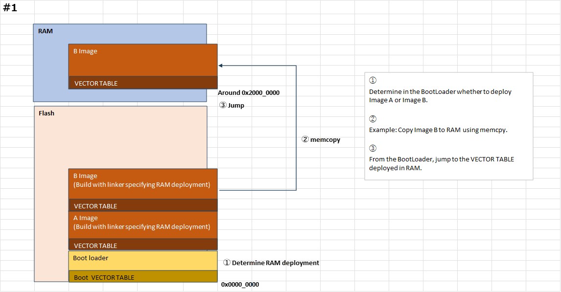
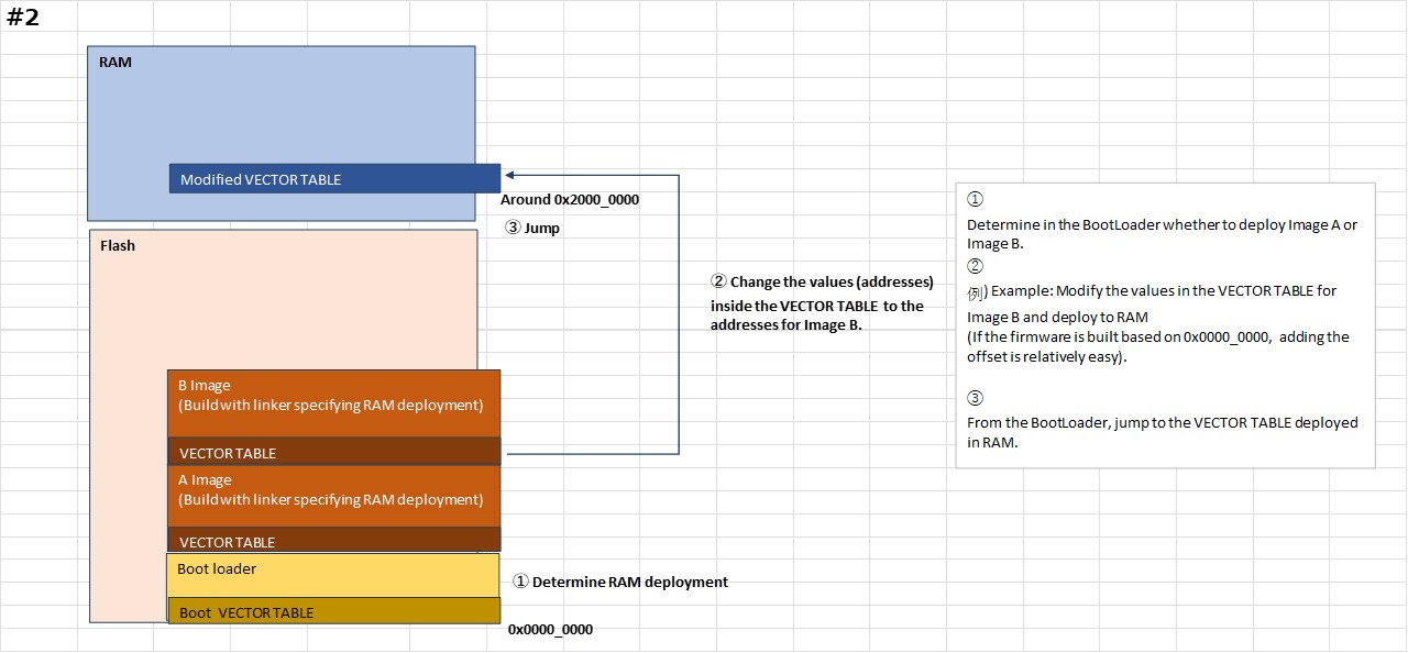
As shown in the diagram below, my customer are considering a configuration where the Flash memory area consists of two images (A and B) and a BootLoader, and the selected image is deployed to RAM for execution.

Q1: Is #1 and #2 feasible?
Q2: If it is feasible, could you please let me know any constraints or concerns?
Q3: Also, could you suggest if there is a better approach?

RAM_excute1.jpg

RAM_excute2.jpg

Additional information / Purpose:
- The goal is to enable firmware (image) switching during operation in the field by deploying to RAM.
- Currently, it is undecided which image (A or B) the user will use, and also undecided which image will be updated during an update process.
- Two sets of table data will be prepared to match the images, and these will also be deployed to RAM.
- Refer: MSPM0G1106: Inquiry About RAM Execution and Release Build on MSPM0G1106 - Arm-based microcontrollers forum - Arm-based microcontrollers - TI E2E support forums 

Best regards,
O.H

  • Hi experts,

    Sorry for rush you. Is there any update?

    Bset regards,
    O.H

  • Hi O.H

    I will look into this case and reply to you tomorrow.

    Regards,

    Zoey

  • Hi  ,

    Why you need to deploy one to RAM for execution?

    For #1 yes, the image B can execute in RAM while  #2 is not, only put the vector table to the SRAM.

    What you need to care about for #1 is that make sure your image complier is based on the RAM address. For example, the vector and other project of image B project is already based on 0x20000200(for example), you can not sure project staring at 0x0000 as the image B.

  • Hi ,

    Thank you for your reply.

    Additional information / Purpose:
    - The goal is to enable firmware (image) switching during operation in the field by deploying to RAM.
    - Currently, it is undecided which image (A or B) the user will use, and also undecided which image will be updated during an update process.
    - Two sets of table data will be prepared to match the images, and these will also be deployed to RAM.

    The above is the reason. At the moment, we have designed it to be flexible.

    What you need to care about for #1 is that make sure your image complier is based on the RAM address. For example, the vector and other project of image B project is already based on 0x20000200(for example), you can not sure project staring at 0x0000 as the image B.

    Let me confirm the above. Does this refer to the compiler's Section settings? If I specify a RAM execution area at the Section settings stage (e.g., ImageB=0x20000200, ImageA=0x20001000), does this mean that ImageB cannot be executed anywhere other than 0x20000200?

    Best regards,
    O.H

  • Hi ,

    Regarding item #2, I have a correction and an additional question.

    The procedures in steps ①–③ are the same. The term "Modified VECTOR TABLE" in step ③ refers to the address of the VECTOR TABLE located in the Flash region that execution will jump to afterward.

    My intention is to make this "Modified VECTOR TABLE" variable, so that the jump destination can be freely selected between the A Image and B Image.

    I am using the sample code located at:
    C:\ti\mspm0_sdk_<version>\examples\nortos\LP_MSPM0G3507\boot_manager
    as a reference, but in the sample code the jump destination VECTOR TABLE is fixed.

    Is the above approach feasible?

    Best regards,
    O.H

  • Hi ,

    Sorry for rush you. Is there any update?

    Best regards,
    O.H

  • Hi O.H

    Sorry for late reply. there might be some errors in E2E email notification.

    The above is the reason. At the moment, we have designed it to be flexible.

    There is no flexible as I can see so far for RAM execution. Why you don't want to execute in Flash?

    Let me confirm the above. Does this refer to the compiler's Section settings? If I specify a RAM execution area at the Section settings stage (e.g., ImageB=0x20000200, ImageA=0x20001000), does this mean that ImageB cannot be executed anywhere other than 0x20000200?

    Yes. You will compiler your code for imageA/B in compiler, right? And this will fix which address to store your function (e.g timer interrupt handler)? And All the interrupt handler address will in noted in interrupt table, CPU will execute and enter into the related address.

    Regards,

    Zoey

  • Hi O.H

    You can not choose which image you need to execute through vector interrupt table. You need change change your PC address to execute different main function. The advantage of storing the interrupt vector table in RAM is that you can freely modify the addresses of each interrupt to jump to a specific interrupt in ImageA or ImageB.

  • Hi Zoey Wei,

    Thank you for your reply.

    Sorry for additional question.

    QRegarding the application area other than the vector table, is my understanding correct that the addresses of the interrupt functions (handlers) included in each image are, by default, assigned as absolute addresses at build time?

    If the build option below (the -ar option) is used, will the addresses be assigned relative instead?

    In the case where only the vector table is placed in RAM, my current understanding from the previous explanations is that the interrupt functions (handlers) of the selected image are called using absolute addresses.
    However, I would like to confirm whether it is possible to access them using relative addresses, or if absolute addressing is the only valid mechanism.

    Best regards,
    O.H

  • Hi O.H

    Yes.

    All is used in absolute address.

    But good news is that if you simply place the interrupt vector table in any location in RAM, you only need to put the table's address in the SCB->VTOR register. When an interrupt occurs, the CPU will jump to the interrupt vector table and obtain the address of the interrupt service routine.

    If you want to use a single interrupt vector table for both image A and image B, then during the switch, you will need to modify the entry addresses of the interrupt service routines in the interrupt vector table. For example, if image A's timer handler is at 0x2000 and image B's timer handler function is at 0x4000, then when switching from A to B, you need to change the timer interrupt address in the interrupt vector table to 0x4000.

    If the build option below (the -ar option) is used, will the addresses be assigned relative instead?

    I can not find related -ar option description in TICLANG. Sorry for that I am not familiar with this. You need to check your complier user guide and check it is feasible. 

  • Hi Zoey Wei,

    But good news is that if you simply place the interrupt vector table in any location in RAM, you only need to put the table's address in the SCB->VTOR register. When an interrupt occurs, the CPU will jump to the interrupt vector table and obtain the address of the interrupt service routine.

    If you want to use a single interrupt vector table for both image A and image B, then during the switch, you will need to modify the entry addresses of the interrupt service routines in the interrupt vector table. For example, if image A's timer handler is at 0x2000 and image B's timer handler function is at 0x4000, then when switching from A to B, you need to change the timer interrupt address in the interrupt vector table to 0x4000.

    Thank you for your reply. I understood.

    Sorry, I forgot the link. The details of the -ar option are listed below, but the details are difficult to understand, so if you have any information, please let me know.

    10.4.5. Linker Output Options — TI Arm Clang Compiler Tools User's Guide

    Best regards,
    O.H

  • Additional information.

    By the way, when I actually set it up in CCS and built it, it seemed like I couldn't set both.

    Actual CCS version is 20.4.1, Clang v5.0 is same.

    Best regards,
    O.H

  • Hi O.H,

    It seems that it is not supported for MSPM0 device? Not sure....As I am not familiar with TIClang, Let me orient this thread to SDTO team for help. Thanks!

    Zoey

  • I apologize for the delay.

    Combining the linker options --relocatable and --absolute_exe  is not supported.  I filed EXT_EP-13217 to have the documentation updated.  You are free to follow it with that link.

    I don't understand everything about your system.  But I understand enough to make this suggestion.  

    The linker supports allocating an output section to load at one address and execute at a different address.  Building on that, two output sections can have the same run address, but different load addresses.  I think this is useful in your case.

    In the tiarmclang online manual, start with the sub-part Using Linker-Generated Copy Tables.  Focus on the sub-part titled Overlay Management Example.  But do not use the operators LOAD_START, RUN_START, or SIZE.  Use copy tables instead.  

    I'm aware of no example on point to your situation.  Something close is in the application note Advanced Linker Techniques for Convenient and Efficient Memory Usage.  The associated examples are for a different processor family, and do not build with current versions of CCS.  But the example source is still worth a look.

    Thanks and regards,

    -George

  • Hi George,

    Thank you for your support. I understood.

    I will review your comments and create a new thread if I have any further questions.

    Best regards,
    O.H