This thread has been locked.

If you have a related question, please click the "Ask a related question" button in the top right corner. The newly created question will be automatically linked to this question.

AM2432: IND-COMMS-SDK: Triple-Buffer of EtherCAT Sub-Device on ICSSG1 seems broken

Part Number: AM2432
Other Parts Discussed in Thread: SYSCONFIG

Hello,

currently we experience issues with the Triple-Buffer of the EtherCAT sub-device (I strongly assume there is a triple-buffer implemented in the PRU code).

  • We are sending FSoE frames embedded in normal EtherCAT PDO data.
  • For the FSoE protocol the following scenario is not allowed:
    • Frame X (e.g. 0x360ace080100) is sent (from EtherCAT slave to EtherCAT master).
    • Then frame Y (0x360aa71b0100).
    • Then in the cycle directly after frame Y, frame X is sent again.
    • So the order is:
      0x360ace080100
      0x360ace080100
      0x360aa71b0100 
      0x360ace080100
      0x360aa71b0100 
      0x360aa71b0100 
    • This is not allowed by the FSoE standard.
  • When we check the log what our application on ARM R5 core writes to the EtherCAT input buffer (in function APPL_InputMapping()), it looks like the following:
    0x360ace080100
    0x360ace080100
    0x360aa71b0100 
    0x360aa71b0100 
    0x360aa71b0100
    0x360aa71b0100
  • So this seems like a typical triple-buffer fail to me. The value 0x360ace080100 is repeated, because it is still present in an older buffer of the triple-buffer, despite the new value 0x360aa71b0100 was already present and sent to the EtherCAT master.
  • Apart from our logging in APPL_InputMapping(), our application code on ARM R5 does not include any double or triple buffers or similar, so the application on R5 has no way to even remember that 0x360ace080100 was sent before 0x360aa71b0100. Therefore to us it is very likely that the triple buffer inside the PRU code is the culprit.
  • The failure is very rare. Sometimes we waited multiple weeks for it to happen. However, it is serious, because the FSoE connection is in error state afterwards.

Our setup is the following:

  • AM2432BSFFHIALXR
  • EtherCAT Sub-Device on ICSSG1 has Revision/Type : x0690, Build : x0542, Firmware Version : 6.5.66
  • However, for other drivers we still use ind_comms_sdk_am243x_09_02_00_24, but we already placed the newest version of the EtherCAT Sub-Device code from ind_comms_sdk_am243x_2025_00_00_08 into it.
  • We use the beckhoff_stack.

We would be grateful for any support here. Are you aware of any issues like ours?

Please feel free to ask, if you need further information.

Kind regards,
Martin

  • Hi Martin,

    Thank you for the above details.

    EtherCAT Sub-Device on ICSSG1 has Revision/Type : x0690, Build : x0542, Firmware Version : 6.5.66

    Are you facing similar issue when using an older EtherCAT firmware, say version 6.5.54 (from ind_comms_sdk_am243x_11_00_00_13) or 6.5.50 (from ind_comms_sdk_am243x_09_00_02_24) ?

    Also let us know the status with the latest EtherCAT firmware shared with you.

    Regards,
    Aaron

  • Hi Aaron,

    we switched to 6.5.66, because we hoped this would resolve the issue, previously we used 6.5.54. At some point we were using  6.5.50, but I do not remember anymore why we changed to 6.5.54.

    To summarize:
    6.5.54 and 6.5.66 have same issue.
    For 6.5.50  I do not know.

    Kind regards,
    Martin

  • Hi Martin,

    To summarize:
    6.5.54 and 6.5.66 have same issue.
    For 6.5.50  I do not know.

    Thank you for the clarification. We will review the particular section in the PRU implementation which may lead to such behavior.

    Regards,
    Aaron

  • Hi Martin,

    An additional query, can I get more details on the test environment? Like the EtherCAT MainDevice used, it's configuration, topology, or any other details which you think can help us in reproducing the issue faster ?

    Regards,
    Aaron

  • Hi Aaron,

    I have written an email to you. However, feel free to ask for any further details.

    Kind regards,

    Martin

  • Thank you Martin. Will review the details you have provided.

    Regards,
    Aaron

  • Hi Aaron,

    sorry for my late response, but I got sick last week. 

    Currently we have 3 Test-Setups:

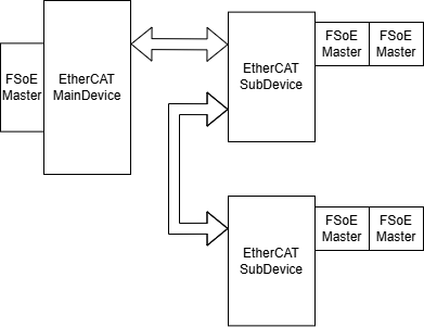
    Topology of Setup 1:


    Topology of Setup 2 and 3:

    The difference between 2 and 3 is that there are different modules attached to the EtherCAT SubDevices (= EtherCAT Couplers), i.e. PDO data sizes are different.

    Setup 1 produces the error most often, but Setup 2 also produced it a few times in the past.

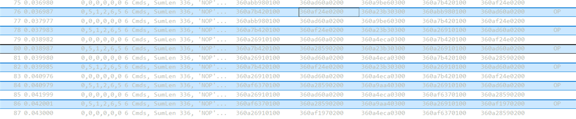
    A few days ago sadly Setup 1 now produced the error again with FW 6.5.72. I have attached the wireshark log (1). This is now really the frame repetition error we are having trouble with. The error where the frame went 0 was probably something unrelated, we at least have never seen before.

    Here you can see the error between packet 76 and 86 at connection 2, see also attachment (1):

    I have also attached a wireshark log (2) where you see the sync manager configuration of Setup 1.

    Test Setup 2 and 3 are running non-stop since last week Tuesday, have not produced an error so far. Currently Setup 2 has the most elaborate logging.

    So from our side we plan to do the following as next steps:

    • Move logging from Setup 2 to Setup 1 (after we have given Setup 2 a bit more time to maybe also produce the error), because error seems to be more consistent on Setup 1. Due to a lack of tracing equipment it is not possible to do full logging on all setups.
    • Given that it was quite a while since setup 2 also produced the error, maybe try Setup 1 without the splitter and see, if there is a difference.
    • I will post a project for a 4th test setup just with an AM243x Launchpad and our EtherCAT MainDevice and therefore our sync manager settings in the next few hours/days. However, it has not produced the error so far.

    As I already said, it is a bit tough that our setups very running often mutliple weeks before the error occured, so it can take quite some time to see it. Currently it is coincidence to me that Setup 1 seem to have the error after just one week (if we ignore the probably unrelated 0 issue).

    (2) setup.7z.txt

    7z��'�B�Jr0���3B]߃�G�C�w�b{�:��M#
    sٵ1B��bߪ�n�B"97��\�����%M��O=&y�~`�8���Y��^��4֐�O�
    r>#4�O7��-�9��@��/=V*tt�y�,!J�M�n���D]�$[��ձt�,�3m�36)�Hv1U�X�Og��'�‚ۉ�iR�#g꾴��Ss���G�r��M�1��kE-�w��`�)�y�I:$q����ǵ6��-b���
    ��N9f#�莁E��TgU�F�	7U-��8�f���y�L�j6,�c���5.W,� �|��>R�Mt�+���A�*#�3���%DY�R6}ov���Z0�v.�"|��	P�^p�hY�D��2��"�̪�l��Yr>�(�K\5�=��H�/4���ڲ��6+oV��>�iUw�T�4�Fz�@�@.h��s�GY�}���������7\|�'b=���~ʚ$xs��7���㡅oI|�in��]Pb��5�lob���=b*�,�3�D���h�L��lx�C�/������by�!$�QTY���:s�1n�.엋湘��N�[NG˦ �o�s3FhJ����W��T�I�*�]~L7m�{ז;1'p���jy:S�\��K�eUc�`q1gg��[���]��-��`��U9Ƌ���� �j��Z�H	<at��q����:}C�wQJ�1��<����u����Pʼn����	N�o��>����ڢ�*M/�;���s�L
    k?a�k\Ʃ�;���^�qcX��DB=� ��\�1�t�
    ��3��H �
    m���mo;���1A��5w��*�����=�r�����g��3�ޜ@W^�Q�4�H.��eըJ����������q�o�u�e:����Ƽ��� ��r���UL��
    3���"�}�
    �8��@Ǥ��%ϥf�Q�a,%??�݄=ʝ����%�_�{�ɲ��)z˲�&�� 7�����>�9!�x5��k�]I g�%mԀ'] 6
    ���0��0v��g߁���pKDl.��ë��m��Q'1.S]z7������t�|������?�,!��M*�1�G���ݪ�OF#_��[�Ѧ��ED�/
    9���#*��t��ǽ'����Js�R���E�ج��4�����VY�5���\�?���)clB!�nb����2h�@1��A
    SJ��H��̿4�I��C~k���``��zX�&��Dy��8�D7�Ѣ����M�����g�[� ��,o���d,��Q��w����D�4��7.@}Ǩ&����w}�”��g;��F�� c�kcJWQ��`x'�qeL9 ��$���=�;���|s�������Ǯ���~a=��fX�3�Q��'��$*�F���M9�ܤ�VE��K����z%�As0�%��>��|�����sNg��e�u���x{�4�N�����Ț��7�%�&�H��/��®	�<(՗w4�1��%�b�0"��a�����J�ɊA��[r�sdw���!+Z�GODA�����o۟;9��9-��j��8��0	���,-M�0��}�N���0K��]"���*�|8�`*��A e�i���<:���c�Bd��Ul��3c:�{��#�z�>h��(Dל\X�;1�:P�ز��o`��#�OSP�Cz'>�@��^=�r/��b��h�F�������*_��z�8șk �s��qg��a;�sw�Hk�~��#V��2��^I&1��uq,Cp���e#[�`iѷ��.L�9���J��~`�3�)�o	l�`��U�:	K��æ��CC��6�j)g0 u>Oy��f��k��W�.�OR�T�a墑��C<j�	S��������,Vด�nth���'�:������ �:h�3������m�xo�aN�3
    �p��3	�Qr����C o ��G�����$t�%¦���[���l4q�H�}�^�Ed�����H�	f��V�n�YILzM4d�iX�~�2��a?�[=��G�M-��P��FU� >�k�-�<���=�w���~&U����6��b��& {}9��Ѫ��tm���,�`Nq�^E���*�W����k�,��m��l͋�m'��7p��X"6����QJ$�6�a�p�����[E�,�gL�1��o�֜��~���N��YL�NE/�-�l��勌V5C��y���ZM[�$�.�����R*����%Kɯ�'����ͷ�vC��m�b�Wt7�<n`���%J�'?t�ߟ����wG����K�y˶t�N�����/_���j�A��b/�6��`��p^HH@z�r�8�F�ɪ��́���6�M2�e{\�Ϡ%+���P:�>l��$�)���"p���мy��P��QV��H�˯��!�C��f��&L}p�
    �-#xJF�wB�q��4�ow���Z;�.�W
    X��7k�
    �eC"+�g���n��O���gj�u�f~����x�Oڷ5y-J��(lM����7s��Y��d�؁´��9�Od�W��<_��a������������Zbָӧ�j}�|;��Yr��b�h8����ubI�3��rF�J��w�}=�U�[�L����ex��u��+�ּc��>�Еw�&"!S�7*/�\D|�P�{�n���$��gs;���%����]��l"����.g�����������D��gH�G�(����^�v��e�+�c��y
    �r^��_.K�����[����/u�2����r�U3�ɇ���`���('i�iV�/�P*c�c���ξvA�W[D��2x�J��/�橇�� ��:�>��g/<9Y#�꒤D���h6�)Й#����K��ʫ!
    ˝���H�D$4P>�oT��9���֔āT.�[�q�w��\Z�t`�
    	 9��<6�(n�$�3`�&<!�/�U?$"���/oZ�����.A�ۙ���c��X��"��z+Е9�'��;��p-PA�ݸxb�������fU_��db��Xԩ�)q�ds2&������ƽ]W�2&�Z�`�Uئ�HD�M�S��-2�M/�lƤ��cW�yz����8�Gϻ���a���/�I�g&Lg�/���l�Y��jT�Z�{�e����e�@<nƊOM���b~խ�s.r�F
    ӕ�r���p%�m7Lٷ~���L:&JR�KSG��<S�����Q��a�ڵ.����di����k��%Y	�<�)g~������y��]�N�|��RX���׍)$�ِ�+�AH�
    �b��_Y��ȁ~&���Kc��&+f�����U���Ջs�8���X�#��2�D�ƵWcx�����ӿu���;ؚ[�PC�8��&*8G���?Ea��3�-Hn��Y�>�Y���~*�x�;�L�F�����q���JE��]4��2�u}����`���]K����gp#{��_�Rr'�<<�[�CV�®�D�Ag�*�H�%Gk_�u�m2�l�^_}}��,�4@�<7�vK<�r�� �
    Z�=!��d����Gkq�l�K�^�6��F��	S��"f�2��#�%�n��J:�{f/�p��)-mM�tY�PVCAN�@ه��VEi��R�gU�W
    爘#6��bo��	a� 
    [�]��ɥ�����|�����D��ܱߌ��j-��^�T��9�>�X���5�p����������2▐uԅ�o9�w]w���)|�q�R�J{�~��E=[�F����I$���w���*���
    =���2:�/oк���e�!sXSDU}>�s���d����.>��+�fT)�����o�����y���&Jj���@\�_׸�0C���e>���f�JQ���3�	^����ң�˝`2�}֧��T�u&�M]nD�a��vY��GX��=�Û7s����YM;
    	/_�&��y��bn��B�j͹q����3��
    �gK\e�W*>���{,/%F��By���R�>��A@K�N�A����ʊ��.RL�͉N�Ƶ���=M7�ְ�xi+D�Y2�� S��?���=��ak��[����x"�N�Ô����F�����d-�����:W��͎�C$�
    	0���v�xYx��Ab]J|��
    0�U��$��{'1���ԕ�x����	ԊđV^��k6|V�	���tO�=*�
    8���Q0�f0=��:;�0��{��f֑��v<}��A���+��LA�1"p�ٵ�AC_���s��悮Ssć�	��
    ]�3�c�ū�,���&<����@�y����/�ij�v�����Wq��W�C=�f?B?����<}���{5 �dN�
    �@%TSUHc�}�?� dP
    ܋V��Ն&!s���ɶ�����,ٙ��=%�Yt�zmr>�ϡu&x��s��u�X�ū׮�?_��sCxn�ё��`P�����\o���#;
    ��J���Y�R����;,c!Fz1�]У�^�4җ�p�w����&��� Z��o���
    ��3��X,�E�λ�M;k�
    I�w�W.E�`�|�)�PG,���Z��_�F��p]a��B��d�fX$���t��O��z^���$��m��Op1Q<	��nm��mG+�Q�`@�~�cʘC^���ŏ�a5��	�<JζF�_�j:�|F�/0�8�Rd����&M�G=�n�ZC=�oz��q�8B�J�>ƻ/�{�g�?�ݭD����$�O3���bH�/a�f`�3�YA+���n�hv�b�v��;ko"�cGY��k��x�ԡ���vk�:8Y[;������2[!��).�xl��)�q{g�����6��T�staA>�|��򶉼M������T?N��R�zDr�p�>��8��ᚼc�FU@�u:�յ�o�P�s���ջrl��|^�\�6Y�9t��ʱ�\M���u�?e]�T3|l�9���
    ��۴�O�N��'�JV�X��K��ѤO�ip��q��%Dn�zS䔭���d���|iE��ij2Z2�_��1�����!��C��?��P��ַ���耪>�S,Pn���2��U2�T�'�#����E�cSI�Gb��koOf@�s�.��(�䡌�U}�1�n�B�nV�'����gu8j�:BC���3���鼽��m_���܂�H���ff��CBU�O��&uࢹ�]�
    ,��]�Ĉ��3Z�V�؊�
    �dW������ɩf�Z(Q.E7ӾL����t'��J"���p�Բ�5�	�oWC�jy����|�FGk���SQ~���2m��ܩ`A���B{F�����f��Ԍ��`eFU����r��ff�s:X��|P9�
    zR�ٵB-�������O�R/a.;)���=�ŎX�����dkE�D�!����?�4�[�?�T-��2����Y�&��P����I];;	uHJ"V�wc�Ày���֠B��WB��		�e�B+�����	#"f>Q�ա�TZ��q�u��l!aY��t$�6X�`�����Z�z��6����=vU�^�
    ���U0�Ã�c{,�/�j��kp<�]ѳ1�E�x�.$�K|�J�F��7u8'oK�J��l���N(޳6*�P_n��H=y@j���b�K!���9g.�y�"�Br�#c"��X#V���h�u%����_�}�����`����G���ћfB���@��sG�Ԍr��S$b��7�Ø�+;�0�ia��2 �%��q��Yp��bjW�%�?1>x;�[0�S��y�X�˜�H�s��M��!v��
    \����ڗ��K��+�<����L���	��De$�=?+���㾮�Yo�2�-�����Qn�"ʛohv{��A,�J6��u�s	Rzp��[c������th޴%>�H��)���N�O�X�NK��n�"�k�;�C��J��v��u��v@�S
    Oj�G{�dH,��Y߂�V'ӿ��I�D�0|З��/��t��>��o���(�@x��v�8�,�S?�ᖚlZd�"������3�^��~����؅����L����K#�x�ig��}?�g�Agk)�S$xK�H���kd�n���4V ����*9�AC�{����⮒���V�;O�d��r��A0���������G&���O+7��U&��9Þ���=x(^3�����9�.ۛN�	�z
    ��L
    	4�[+Y�E1Wy1�8�%�r��]��U��:oA㛖"�;4��Z�����2.YP�v�E�֔K��p�f(;g�B��v���y����\�wu)� ��&��ra�y��ӞY�Ǫ�ן<Y���3�}�Ca�&��3������U4nK9g	eok{q/YvNe��e#�K����r�%&yP.z���W@������$�y^~QR�~����Lѝ��m��$�F5<�j��ݞ]G��Ӫ.?�_T~d2Gt��SV���vC�l��TV�B�)Z���<�[�xdxyR�}S��#4��/.�Q�Ԧ�O��2��&PT�|B̙�����bA��-3d�_PhV��|{�TY�a���jOp�]���8*���Υ��(mHT_�U؇�t�I�M:I��D&@��u��[�G3�0g
    ��m�=-�6 ����L����cv��X?�ta-܃#͝&�M*����eqɼJ=����]���Sc�u�8��jw]j�?l�5]���\��э�<Bvhze�v���]�T��jIE�A]c��h���*aDE4� ���-Ug���&���ӆ�G٬�����O�\���*J��U��K0��0�����8���)1l]N�"z�|<'M围��-@�:�阮�?a�Mx�mj��q�k-j�,E�	ܕ!_�_8L�[rQ9�:'e7%}qm�Ş�J����x�:)<����D�T���*z	�@��Rr��0'.��UWz\�9Y�Z��jSZ�L|�c8��N��F����WD3��[�
    �tS83P-��3"�KG&
    [��f@U+�$�$}�x��ܾ�p� (Gy�R�{j��,:�������t�2�Yi�I��.����%�k�;r#����+���M�t��E��h���1�����5��*O����Y}N�7�����]�|nh�Ǐ����m����^�K��	��R̳'�6S�IY6F���#?�B8�[�GI�͢��3��
    (AV`�th6&��3D�J���|5���*:?�/�T9��V��ۢ\#;�zR�<^^�jb&�u�t���m��2>S�n�I����ј�o�]�F�&�O]��+���db��.���׊�+57�d2L�$�׮=�Nm�>B�׹e޵�s�z7���m]V����C���^촉��{Pr��6SYX(�ҵ�F�D���M�^���|���%U��j~Ij�Ή��v@]G��5O��$�Z��U�{ү��*S�ͯ�{�v)�V$ҊAd̋P�<��P�:4�(�>;M���@lWmn�Vc䘞{޻��GY��p��)LRr�%����K}/�Qv*��[�jc��K(��#X��CE��<��S��nA�wA��"�����ƒ%���RǓ^�+�cO& a���ڼz]F���7ߛͧ�W���6n������9�Ez����E��mw}��������C��u�܆
    ����[��{��yG��L]ŏe��G�a����[�"�ꖸ�n�;��u�
    �c*���D��V����2�6�oͶ!�	Lb��Pp���E�=`_8��`+{w{_X� ���[1������^
    ����'R��$���<�
    ݒ�$�/��4_�|����h�Z����O�0���o�%�b{PNw��s�ȝG���Ǭ.�a����q��Ö;mO&�H[K�-h�	�J!!�4�
    ���	-(1) fsoe_error.pcapng
    �KLmɎ� 

    (The two files are 7z files, just renamed to .txt to bypass file filter)

    Thank you for your support.

    Kind regards,

    Martin

  • Hi Martin,

    So from our side we plan to do the following as next steps:

    Thank you for the details and the next steps. One question I had was that, is this seen without FSoE transaction? I mean assuming no FSoE Master, is the swap issue seen with, say TwinCAT free run? 

    The error where the frame went 0 was probably something unrelated, we at least have never seen before.

    Yes correct. From the logs you provided, it looked like the SubDevice/node went out of network based on the datagram WKC values.

    Regards,
    Aaron

  • Hi Aaron,

    Just to answer your previous question quick:
    This error also occurs without FSoE connections. The error is basically that older input data is read from one sub-device after more recent data was already present in the cycle before. Hence, if you would just use a counter instead of an FSoE packet then the error would look like the following: 0, 1, 2, 3, 2, 5, 6, ...
    We have only tested with DC synchon mode and not FreeRun.

    However, yesterday one of my setups with logging inside "HW_EscWriteIsr()" and "HW_EscReadIsr()" was able to reproduce the error:

    • The setup is topology 2.
    • The error occured for an FSoE connection between the two FSoE masters attached to the same Bus-Coupler (= EtherCAT sub-device). This is good, because this way we see the faulty FSoE connection in input and output data of the same sub-device.
    • input data bsp_write() writes to the addresses 0x2400, 0x24EC and 0x2476.
    • output data bsp_read() reads from the addresses 0x1400, 0x149C and 0x144E.
    • Usually this addresses switch per cycle in a constant pattern like: 0x2400, 0x24EC, 0x2476, 0x2400, 0x24EC, 0x2476, 0x2400, ...
    • But close before our error can be observed in the output data (again this particular FSoE connection (0x360003590200)/(0x3600BD6B0200) occurs in input and output data), when input data is written via bsp_write(), bsp_get_process_data_address() returned the same address for two cycles in a row, so the pattern was: 0x2400, 0x24EC, 0x2476, 0x2400, 0x24EC, 0x24EC, 0x2400, 0x2476, 0x24EC, 0x2400, 0x2476, 0x24EC, 0x2400.
    • So there are two things that look faulty:
      • two times 0x24EC for consecutive cycles looks like an error.
      • the pattern changed from [0x2400, 0x24EC, 0x2476] to [0x2400, 0x2476, 0x24EC].
    • Together with the FSoE connection in question this looks like the following:
      • Input data:
        (8) 0x2476,  0x3600BD6B0200   (most recent packet)
        (7) 0x2400,  0x3600BD6B0200
        (6) 0x24EC, 0x3600BD6B0200

        (5) 0x24EC, 0x3600BD6B0200
        (4) 0x2400,  0x3600BD6B0200
        (3) 0x2476,  0x360003590200
        (2) 0x24EC, 0x360003590200
        We can see here the legitimate change of FSoE data from 0x360003590200 to 0x3600BD6B0200 and also the (faulty) repetition of 0x24EC.
      • Output data:
        (8) 0x1400, 0x3600BD6B0200   (most recent packet)
        (7) 0x144E, 0x3600BD6B0200   
        (6) 0x149C, 0x360003590200
        (5) 0x1400, 0x3600BD6B0200
        (4) 0x144E, 0x360003590200
        (3) 0x149C, 0x360003590200
        (2) 0x1400, 0x360003590200
        Here the addresses [0x1400, 0x149C, 0x144E] behave as expected. But we can see here an error when FSoE data changes from 0x360003590200 to 0x3600BD6B0200, it should be smooth as for the input data (because basically this is the input data just sent back from the master to the slave after it has been sent to the master by the same slave).
    • I am now very confident that the root cause is that bsp_get_process_data_address() return the same address 0x24EC for two consecutive cycles. I mean this is wrong, is it?
    • Below my original measurements done with Saleae (interpreted using Logic 2) will follow as a collection of pictures and also the .sal file.
    • Especially picture 3 is interessting for timing/temporal relations, but I can tell you that there is nothing conspicuous. The timing looks as it should be. We have 1ms EtherCAT bus cycle time and the distance between each call of HW_EscWriteIsr() and HW_EscReadIsr() inside PDO_InputMapping() and PDO_OutputMapping() is approx 1ms (+- 10us).
    • I also will attach the code of tiescbsp.c file, it is the file from the latest SDK. You sent me newer header files for the code inside ICSSG1, but never a newer tiescbsp.c or tieschw.c, I hope you did not forget.
    • I will also attach tieschw.c file from latest SDK.
    • If you search for DEBUG_FSOE_TRACE in the files you will see my logging locations. Also expect some neglectable changes in the files like include file paths have changed.
    • I have no wireshark log for this test setup, but I do not think it is needed.

    So to summarize can you explain to me the following:

    • Why is bsp_get_process_data_address() returning the same address at two consecutive cycles? Is this a bug?
    • And why is bsp_get_process_data_address() implemented the way it is, if the intension is just alternating between 3 addresses?

    Attachments:
    Picutre 1:

    Picture 2:


    Picture 3:

    Saleae (Logic 2) log:
    finally_bug_short2.sal.txt


    tieschw.c:

    /*
     *  Copyright (C) 2021 Texas Instruments Incorporated
     *
     *  Redistribution and use in source and binary forms, with or without
     *  modification, are permitted provided that the following conditions
     *  are met:
     *
     *    Redistributions of source code must retain the above copyright
     *    notice, this list of conditions and the following disclaimer.
     *
     *    Redistributions in binary form must reproduce the above copyright
     *    notice, this list of conditions and the following disclaimer in the
     *    documentation and/or other materials provided with the
     *    distribution.
     *
     *    Neither the name of Texas Instruments Incorporated nor the names of
     *    its contributors may be used to endorse or promote products derived
     *    from this software without specific prior written permission.
     *
     *  THIS SOFTWARE IS PROVIDED BY THE COPYRIGHT HOLDERS AND CONTRIBUTORS
     *  "AS IS" AND ANY EXPRESS OR IMPLIED WARRANTIES, INCLUDING, BUT NOT
     *  LIMITED TO, THE IMPLIED WARRANTIES OF MERCHANTABILITY AND FITNESS FOR
     *  A PARTICULAR PURPOSE ARE DISCLAIMED. IN NO EVENT SHALL THE COPYRIGHT
     *  OWNER OR CONTRIBUTORS BE LIABLE FOR ANY DIRECT, INDIRECT, INCIDENTAL,
     *  SPECIAL, EXEMPLARY, OR CONSEQUENTIAL DAMAGES (INCLUDING, BUT NOT
     *  LIMITED TO, PROCUREMENT OF SUBSTITUTE GOODS OR SERVICES; LOSS OF USE,
     *  DATA, OR PROFITS; OR BUSINESS INTERRUPTION) HOWEVER CAUSED AND ON ANY
     *  THEORY OF LIABILITY, WHETHER IN CONTRACT, STRICT LIABILITY, OR TORT
     *  (INCLUDING NEGLIGENCE OR OTHERWISE) ARISING IN ANY WAY OUT OF THE USE
     *  OF THIS SOFTWARE, EVEN IF ADVISED OF THE POSSIBILITY OF SUCH DAMAGE.
     */
    
    /* ========================================================================== */
    /*                             Include Files                                  */
    /* ========================================================================== */
    
    #ifndef DISABLE_UART_PRINT
    #include <stdio.h>
    #endif
    
    #include "tieschw.h"
    #include <tiescsoc.h>
    
    #include "debug/debug.h"
    
    extern uint32_t pd_read_addr_err, pd_write_addr_err;
    
    /*--------------------------------------------------------------------------------------
    ------
    ------  local Types and Defines
    ------
    --------------------------------------------------------------------------------------*/
    typedef struct
    {
        uint16_t PhysicalStartAddress;
        uint16_t Length;
        uint8_t Settings[4];
    } __attribute__((packed)) TSYNCMAN;
    
    /*-----------------------------------------------------------------------------------------
    ------
    ------  local variables and constants
    ------
    -----------------------------------------------------------------------------------------*/
    TSYNCMAN TmpSyncMan;
    uint16_t nAlEventMask;
    
    /*-----------------------------------------------------------------------------------------
    ------
    ------  local functions
    ------
    -----------------------------------------------------------------------------------------*/
    
    
    /*-----------------------------------------------------------------------------------------
    ------
    ------  functions
    ------
    -----------------------------------------------------------------------------------------*/
    
    
    /////////////////////////////////////////////////////////////////////////////////////////
    /**
    \return  0 if initialization was successful
    
               \brief   This function intializes the EtherCAT Slave Interface.
    *////////////////////////////////////////////////////////////////////////////////////////
    
    uint8_t HW_Init(void)
    {
        uint16_t u16PdiCtrl;
        int32_t status = SystemP_FAILURE;
        bsp_params bspInitParams;
    
        /* the memory interface to the ESC, the ESC-interrupt and the ECAT-timer for the
           watchdog monitoring should be initialized here microcontroller specific */
    
        tiesc_socParamsInit(&bspInitParams);
    
        status = bsp_init(&bspInitParams);
    
        DebugP_assert(status == SystemP_SUCCESS);
    
        /* we have to wait here, until the ESC is started */
        do
        {
            HW_EscReadWord(u16PdiCtrl, ESC_ADDR_PDI_CONTROL);
            u16PdiCtrl = SWAPWORD(u16PdiCtrl) & 0xFF;
    
        }
        while((u16PdiCtrl != ESC_PDI_INTERFACE_ON_CHIP_BUS)
                && (u16PdiCtrl !=
                    ESC_PDI_INTERFACE_SPI_SLAVE));    //Looking for onchip bus or SPI Slave
    
        /* Reading ESC Revision and Build */
        uint16_t build, revision;
        HW_EscReadWord(revision, ESC_ADDR_REV_TYPE);
        HW_EscReadWord(build, ESC_ADDR_BUILD);
        tiesc_displayEscVersion(revision, build);
    
        bsp_start_esc_isr(pruIcss1Handle);
    
        return 0;
    }
    
    void HW_Release(void)
    {
        bsp_exit(pruIcss1Handle);
    }
    
    void HW_EscRead(uint8_t *pData, uint16_t Address, uint16_t Len)
    {
        bsp_read(pruIcss1Handle, pData, Address, Len);
        bsp_pdi_post_read_indication(pruIcss1Handle, Address, Len);
    }
    
    void HW_EscReadIsr(uint8_t *pData, uint16_t Address, uint16_t Len)
    {
        int16_t sm_index;
        uint16_t ActAddress = bsp_get_process_data_address(pruIcss1Handle, Address, Len,
                              &sm_index);
    
        if(ActAddress < ESC_ADDR_MEMORY)
        {
            pd_read_addr_err++;
            return;
        }
    
        bsp_read(pruIcss1Handle, pData, ActAddress, Len);
    
        bsp_process_data_access_complete(pruIcss1Handle, Address, Len, sm_index);
    
    #ifdef DEBUG_FSOE_TRACE
        Debug_uartAddTaskTrace(0xFE, true);
        Debug_uartAddTaskTrace(0xFE, true);
        Debug_uartAddTaskTrace(((uint8_t*)&ActAddress)[0], true);
        Debug_uartAddTaskTrace(((uint8_t*)&ActAddress)[1], true);
    
        extern struct {
            uint32_t byteOffset;
            uint32_t byteSize;
        } gOutputFsoeFrames[2];
    
        for(uint32_t j = 0; j < gOutputFsoeFrames[0].byteSize; j++)
        {
            uint8_t *dd = (uint8_t*)pData + gOutputFsoeFrames[0].byteOffset + j;
            Debug_uartAddTaskTrace(*dd, true);
        }
        for(uint32_t j = 0; j < gOutputFsoeFrames[1].byteSize; j++)
        {
            uint8_t *dd = (uint8_t*)pData + gOutputFsoeFrames[1].byteOffset + j;
            Debug_uartAddTaskTrace(*dd, true);
        }
    #endif
    }
    
    uint8_t __HW_EscReadByteIsr(PRUICSS_Handle pruIcssHandle, uint16_t Address)
    {
        uint8_t ByteValue;
        int16_t sm_index;
        uint16_t ActAddress = bsp_get_process_data_address(pruIcssHandle, Address, 1,
                              &sm_index);
    
        if(ActAddress < ESC_ADDR_MEMORY)
        {
            pd_read_addr_err++;
            return 0;
        }
    
        ByteValue = bsp_read_byte_isr(pruIcssHandle, ActAddress);
    
        bsp_process_data_access_complete(pruIcssHandle, Address, 1, sm_index);
    
        return ByteValue;
    }
    uint16_t __HW_EscReadWordIsr(PRUICSS_Handle pruIcssHandle, uint16_t Address)
    {
        uint16_t WordValue;
        int16_t sm_index;
        uint16_t  ActAddress;
        ActAddress = bsp_get_process_data_address(pruIcssHandle,
                     Address, 2, &sm_index);
    
        if(ActAddress < ESC_ADDR_MEMORY)
        {
            pd_read_addr_err++;
            return 0;
        }
    
        WordValue = bsp_read_word_isr(pruIcssHandle, ActAddress);
    
        bsp_process_data_access_complete(pruIcssHandle, Address, 2, sm_index);
        return WordValue;
    }
    
    uint32_t __HW_EscReadDWordIsr(PRUICSS_Handle pruIcssHandle, uint16_t Address)
    {
        uint32_t DWordValue;
        int16_t sm_index;
        uint16_t ActAddress = bsp_get_process_data_address(pruIcssHandle, Address, 4,
                              &sm_index);
    
    
        if(ActAddress < ESC_ADDR_MEMORY)
        {
            pd_read_addr_err++;
            return 0;
        }
    
        DWordValue = bsp_read_dword_isr(pruIcssHandle, ActAddress);
    
        bsp_process_data_access_complete(pruIcssHandle, Address, 4, sm_index);
    
        return DWordValue;
    }
    void HW_EscReadMbxMem(uint8_t *pData, uint16_t Address, uint16_t Len)
    {
        t_sm_properties *p_sm_properties = bsp_get_sm_properties(MAILBOX_WRITE);
        bsp_pdi_mbx_read_start(pruIcss1Handle);
        bsp_read(pruIcss1Handle, pData, Address, Len);
    
        if(Len >= p_sm_properties->length - 2)
        {
            bsp_pdi_mbx_read_complete(pruIcss1Handle);
        }
    }
    
    void HW_EscWrite(uint8_t *pData, uint16_t Address, uint16_t Len)
    {
        bsp_write(pruIcss1Handle, pData, Address, Len);
        bsp_pdi_write_indication(pruIcss1Handle, Address, Len, 0);
    }
    
    void HW_EscWriteIsr(uint8_t *pData, uint16_t Address, uint16_t Len)
    {
        int16_t sm_index;
        uint16_t ActualAddr = bsp_get_process_data_address(pruIcss1Handle, Address, Len,
                              &sm_index);
    
        if(ActualAddr < ESC_ADDR_MEMORY)
        {
            pd_write_addr_err++;
            return;
        }
    
    #ifdef DEBUG_FSOE_TRACE
        Debug_uartAddTaskTrace(0xFF, true);
        Debug_uartAddTaskTrace(0xFF, true);
        Debug_uartAddTaskTrace(((uint8_t*)&ActualAddr)[0], true);
        Debug_uartAddTaskTrace(((uint8_t*)&ActualAddr)[1], true);
    
        extern struct {
            uint32_t byteOffset;
            uint32_t byteSize;
        } gInputFsoeFrames[2];
    
        for(uint32_t j = 0; j < gInputFsoeFrames[0].byteSize; j++)
        {
            uint8_t *dd = (uint8_t*)pData + gInputFsoeFrames[0].byteOffset + j;
            Debug_uartAddTaskTrace(*dd, true);
        }
        for(uint32_t j = 0; j < gInputFsoeFrames[1].byteSize; j++)
        {
            uint8_t *dd = (uint8_t*)pData + gInputFsoeFrames[1].byteOffset + j;
            Debug_uartAddTaskTrace(*dd, true);
        }
    #endif
    
        bsp_write(pruIcss1Handle, pData, ActualAddr, Len);
    
        bsp_process_data_access_complete(pruIcss1Handle, Address, Len, sm_index);
    
    }
    
    void HW_EscWriteDWord(uint32_t DWordValue, uint16_t Address)
    {
        t_sm_properties *p_sm_properties = bsp_get_sm_properties(MAILBOX_READ);
        bsp_write_dword(pruIcss1Handle, DWordValue, Address);
    
        if(Address == (p_sm_properties->physical_start_addr + p_sm_properties->length
                       - 4))
        {
            bsp_pdi_mbx_write_complete(pruIcss1Handle);
        }
    
        else
        {
            bsp_pdi_write_indication(pruIcss1Handle, Address, sizeof(uint32_t),
                                     (uint16_t)DWordValue);
        }
    }
    
    void HW_EscWriteDWordIsr(uint32_t DWordValue, uint16_t Address)
    {
        int16_t sm_index;
        uint16_t ActualAddr = bsp_get_process_data_address(pruIcss1Handle, Address, 4,
                              &sm_index);
    
        if(ActualAddr < ESC_ADDR_MEMORY)
        {
            pd_write_addr_err++;
            return;
        }
    
        bsp_write_dword(pruIcss1Handle, DWordValue, ActualAddr);
        bsp_process_data_access_complete(pruIcss1Handle, Address, 4, sm_index);
    
    }
    void HW_EscWriteWord(uint16_t WordValue, uint16_t Address)
    {
        t_sm_properties *p_sm_properties = bsp_get_sm_properties(MAILBOX_READ);
        bsp_write_word(pruIcss1Handle, WordValue, Address);
    
        if(Address == (p_sm_properties->physical_start_addr + p_sm_properties->length
                       - 2))
        {
            bsp_pdi_mbx_write_complete(pruIcss1Handle);
        }
    
        else
        {
            bsp_pdi_write_indication(pruIcss1Handle, Address, sizeof(uint16_t), WordValue);
        }
    }
    
    void HW_EscWriteWordIsr(uint16_t WordValue, uint16_t Address)
    {
        int16_t sm_index;
        uint16_t ActualAddr = bsp_get_process_data_address(pruIcss1Handle, Address, 2,
                              &sm_index);
    
        if(ActualAddr < ESC_ADDR_MEMORY)
        {
            pd_write_addr_err++;
            return;
        }
    
        bsp_write_word(pruIcss1Handle, WordValue, ActualAddr);
        bsp_process_data_access_complete(pruIcss1Handle, Address, 2, sm_index);
    
    }
    
    void HW_EscWriteByte(uint8_t ByteValue, uint16_t Address)
    {
        t_sm_properties *p_sm_properties = bsp_get_sm_properties(MAILBOX_READ);
        bsp_write_byte(pruIcss1Handle, ByteValue, Address);
    
        if(Address == (p_sm_properties->physical_start_addr + p_sm_properties->length
                       - 1))
        {
            bsp_pdi_mbx_write_complete(pruIcss1Handle);
        }
    
        else
        {
            bsp_pdi_write_indication(pruIcss1Handle, Address, sizeof(uint8_t), ByteValue);
        }
    
    }
    
    void HW_EscWriteByteIsr(uint8_t ByteValue, uint16_t Address)
    {
        int16_t sm_index;
        uint16_t ActualAddr  = bsp_get_process_data_address(pruIcss1Handle, Address, 1,
                               &sm_index);
    
        if(ActualAddr < ESC_ADDR_MEMORY)
        {
            pd_write_addr_err++;
            return;
        }
    
        bsp_write_byte(pruIcss1Handle, ByteValue, ActualAddr);
    
        bsp_process_data_access_complete(pruIcss1Handle, Address, 1, sm_index);
    }
    
    void HW_EscWriteMbxMem(uint8_t *pData, uint16_t Address, uint16_t Len)
    {
        t_sm_properties *p_sm_properties = bsp_get_sm_properties(MAILBOX_READ);
    
        //Do not write to mailbox if already full
        if((bsp_read_byte(pruIcss1Handle,
                          ESC_ADDR_SM1_STATUS) & SM_STATUS_MBX_FULL))
        {
            return;
        }
    
        bsp_pdi_mbx_write_start(pruIcss1Handle);
        bsp_write(pruIcss1Handle, pData, Address, Len);
    
        if(Len >= p_sm_properties->length - 2)
        {
            bsp_pdi_mbx_write_complete(pruIcss1Handle);
        }
    
    }
    
    void HW_RestartTarget(void)
    {
        tiesc_bspSoftReset();
    }
    void HW_SetLed(uint8_t RunLed, uint8_t ErrLed)
    {
        tiesc_setRunLed(RunLed);
        tiesc_setErrorLed(ErrLed);
    }
    
    unsigned int HW_GetTimer()
    {
        return bsp_get_timer_register();
    }
    
    void HW_ClearTimer()
    {
        bsp_clear_timer_register();
    }
    
    uint16_t HW_EepromReload()
    {
        uint16_t retval;
        retval = bsp_eeprom_emulation_reload(pruIcss1Handle);
        return retval;
    }


    tiescbsp.c:
    tiescbsp.c

    Thank you for your support.

    Kind regards,
    Martin

  • Hi Martin,

    Thank you for the additional details. I'll review them and get back to you by Monday.

    Meanwhile, is it possible to share the ESC Error counters (0x0300 - 0x030D) from the SubDevice side and also can you monitor for Lost frames or CRC errors from the MainDevice side when this buffer switching issue occurs?

    There are chances that the buffer switching may fail if there are errors in the packet transmission (MainDevice to SubDevice transmission).

    Regards,
    Aaron

  • Hi Aaron,

    sure we can log a few more things, but I personally doubt that there are frames lost, because, if you remember previous wireshark logs, which showed the same error, we never saw anything in the wireshark log that indicates that a frame was lost or misunderstood. Or did you spot anything in the wireshark log?
    Then the buffer switching fail occurs on the input data (i.e. SubDevice --> MainDevice).

    However, I will move the EtherCAT analyzer to setup 2, so we have the Saleae logs and the wireshark log on the same device for the same error next time. Also I will try to log the ESC error counters and other things, which are maybe interesting, now that I know the setup does reproduce the error. 

    Then a few other things which are maybe interesting for you:

    • EtherCAT: ICSSG1 core clock is set to 200MHz in SysCfg. IEP Clk sync is enabled and therefore IEP clk is also 200MHz.
    • Sigmatek custom bus: ICSSG0 core clock is set to 333MHz in SysCfg. IEP Clk sync is enabled and therefore IEP clk is also 333MHz.
    • We do use VoE (Vendor Specific over EtherCAT) extensively during OP. So assume that additonally to the sync managers responsible for PDOs, the mailbox (sync manager 0 and 1) is also quite busy.

    Thank you for your support.

    Kind regards,
    Martin

  • PS: Because I stumbled upon it myself again: 200MHz for ICSSG1 and 333MHz for ICSGG0 seem to be not compatible according to newer SysCfg Tools. However, as far as I have observed ICSSG0 is 333MHz and ICSSG1 gets likely defaulted to some other frequency. From a previous support issue I remember that the EtherCAT FW detects its clore clock frequency and adapts to it automatically. This is still correct, is it? Nevertheless which clock frequency would you suggest for ICSSG1, given that ICSGG0 is at 333MHz?

  • Hi Martin,

    I believe you're getting this error when using 2 different frequencies for ICSSG0 and ICSSG1:

    Looking at the PRU-ICSSG integration diagrams (Figures 6-20 and 6-21 in the TRM), both ICSSG0 and ICSSG1 share common clock source inputs from the PLL blocks (PLL0, PLL2).

    The SysCfg constraint means that both ICSSG instances must be configured to use the same clock source selection (e.g., both from MAIN_PLL0_HSDIVX_CLKOUT).

    For your configuration:
    - If ICSSG0 is at 333MHz, you should configure ICSSG1 to also select 333MHz

    The TRM section 6.4.3 referenced in the error should provide more details on the valid clock source combinations for PRU-ICSSG.

    Regards,
    Aaron

  • Hi Martin,

    Following up on my previous statement, few additional points to note is that ICSSG0 and ICSSG1 cannot use the same PLLs for different frequencies. Only the following combination of clock frequencies for ICSSG0 and ICSSG1 is allowed:

    ICSSG0 ICSSG1
    200MHz 200MHz, 225MHz, 300MHz
    225MHz 200MHz, 225MHz, 250MHz, 333MHz
    250MHz 225MHz, 250MHz, 300MHz
    300MHz 200MHz, 250MHz, 300MHz, 333MHz
    333MHz 225MHz, 300MHz, 333MHz

    Hope this makes the configuration clear.

    Regards,
    Aaron

  • Hi Aaron,

    thank you very much for the clarification. Ironically it was planed already by us to set all ICSSG frequencies to 333MHz, but the Triple-Buffer failures delayed that step. However, hopefully it is really solved so simply. I will patch the test setups and let's see what the next weeks will bring. I would wait a few weeks before marking the issue as resolved. I hoipe this is ok.

    Thank you for your support.

    Kind regards,
    Martin

  • Hi Martin,

    However, hopefully it is really solved so simply. I will patch the test setups and let's see what the next weeks will bring. I would wait a few weeks before marking the issue as resolved. I hoipe this is ok.

    Yes absolutely. But do you think the clock frequency mismatch between ICSS instances can lead to the triple buffer issue? I'm just trying to understand the test scenario here.

    Regards,
    Aaron

  • Hi Aaron,

    if both ICSSGs are configured with valid frequencies, then I would expect it to work without issues (so e.g. 200MHz and 300MHz should be fine). However, ICSSG0 must be set to 333MHz. So only 225MHz, 300MHz, 333MHz are possible for ICSSG1. In tiescbsp.h file there are various defines for TIESC for 333MHz (e.g. TIESC_PRUICSS_CLOCK_FREQUENCY_333_MHZ), 250MHz and 200MHz. But not a single define for 225MHz or 300MHz, so I would assume now that 225MHz and 300MHz are not legitimate frequencies for ESC at all, but I assume you know that better than me (?). This is why we plan to use 333MHz.

    Then previously with the older syscfg tool ICSSG1 was set to 200 and ICSSG0 to 333, the old tool had no problems with that, but I assume that ICSSG1 was never really set to 200, but silently set to some other frequency. You could test this yourself what the final values in PLL and MUX registers will be when you configure an old syscfg tool to 200 and 333. Maybe the frequency for ICSSG1 was silently set to e.g. 225, which is (not ?) allowed for ESC.

    Then the syscfg tool definitely did some defines like frequencies for ICSSG clore clock and IEP counter, which were set for 200, given that the final frequency maybe was not 200, this could also be a reason for a fault.

    Then we did already learn from another support topic that it is recommended to set the IEP to the same frequency as the ICSSG core clock otherwise it is difficult to read the 64 bit counter of IEP correctly (there is a chip errata about this). because of the invalid 200MHz setting, I am not sure if this was the case for ICSSG1.

    In general ICSSG0 and ICSSG1 do not interact with each other, only the Beckhoff SSC interacts with ICSSG1 (run on core R0) and only custom code on R1 interacts with ICSSG0.

    So to summarize: I do have hope that setting everything to 333MHz maybe resolve this issue, but I would not be suprised, if it changes nothing. 

    Basically I understood your last replies in the way that you think the different frequencies are maybe a problem, so you gave me hope that the solution is probably that simple.

    In case you want any further information, please feel free to ask? Currently I am still trying to reproduce the Triple-Buffer failure with both Saleae log and Wireshark, so that we can look for e.g. lost frames, but currently our test setups are not producing any errors,  as already said sometimes this can take up to multiple weeks.

    Thank you for your support.

    Kind regards,
    Martin

  • Hi Martin,

    But not a single define for 225MHz or 300MHz, so I would assume now that 225MHz and 300MHz are not legitimate frequencies for ESC at all, but I assume you know that better than me (?). This is why we plan to use 333MHz.

    Correct. Do note that for AM243x and AM64x, only 200MHz and 333MHz is supported by the EtherCAT firmware.

    The firmware configures all the timing related registers internally based on the value in the above mentioned register. This register is configured based on the Sysconfig clock frequency chosen by the user.

    Then we did already learn from another support topic that it is recommended to set the IEP to the same frequency as the ICSSG core clock otherwise it is difficult to read the 64 bit counter of IEP correctly (there is a chip errata about this). because of the invalid 200MHz setting, I am not sure if this was the case for ICSSG1.

    Correct.

    Basically I understood your last replies in the way that you think the different frequencies are maybe a problem, so you gave me hope that the solution is probably that simple.

    Apologies for the confusion. I was more of clarifying the clock frequency configuration based on your additional query. If you choose a clock frequency other than 333MHz for ICSSG1, the value in 0x0E34 (PRU Clock Frequency Selection Register) remains 0, resulting in the EtherCAT PRU firmware configuring 200MHz for the internal registers (default).

    We'll see with the current setup of correct Clock frequency if the triple buffer issue is still observed.

    Regards,
    Aaron

  • Hi Martin,

    I've unlocked this thread to help you provide your response for the triple buffer issue.

    Could you confirm once if the issue is resolved with the EtherCAT firmware shared over mail or was it resolved by running the default firmware with PRU Clock frequency for EtherCAT core running at 333MHz?

    Regards,
    Aaron

  • Hi Aaron,

    we had two test setups running. For both the EtherCAT core clock was set to 333MHz. One setup used the default FW the other one your patched FW. Neither produced the error. So I assume using 333MHz is enough to fix the issue.

    So thank you, and I am sorry for bothering you with this mistake for running EtherCAT core with 200MHz. 200MHz was simply the default and it was overlooked that it had to be changed, if the other ICSSG clock is set to 333MHz.

    Kind regards,
    Martin

  • Hi Aaron,

    unfortunately a few days ago this error occured again on one of our test setups (setup 2) with firmware 6.5.74 and ICSSG1 clock set to 333MHz. So you can still cnsider everything in this thread valid until the point where we started to talk about the clock frequency of ICSSG1.

    Especially that, if there is an inconsistency in the addresses returned by bsp_get_process_data_address(), then the triple buffer might fail. Fail means that data 2 cycles old data is sent (to the master), despite in the previous cycle already new data has been sent. 

    My post containing the following information is a good reminder of what actually happens (I do not know how to quote posts):

    • Together with the FSoE connection in question this looks like the following:
      • Input data:
        (8) 0x2476,  0x3600BD6B0200   (most recent packet)
        (7) 0x2400,  0x3600BD6B0200
        (6) 0x24EC, 0x3600BD6B0200
        (5) 0x24EC, 0x3600BD6B0200
        (4) 0x2400,  0x3600BD6B0200
        (3) 0x2476,  0x360003590200
        (2) 0x24EC, 0x360003590200
        We can see here the legitimate change of FSoE data from 0x360003590200 to 0x3600BD6B0200 and also the (faulty) repetition of 0x24EC.
      • Output data:
        (8) 0x1400, 0x3600BD6B0200   (most recent packet)
        (7) 0x144E, 0x3600BD6B0200   
        (6) 0x149C, 0x360003590200
        (5) 0x1400, 0x3600BD6B0200
        (4) 0x144E, 0x360003590200
        (3) 0x149C, 0x360003590200
        (2) 0x1400, 0x360003590200
        Here the addresses [0x1400, 0x149C, 0x144E] behave as expected. But we can see here an error when FSoE data changes from 0x360003590200 to 0x3600BD6B0200, it should be smooth as for the input data (because basically this is the input data just sent back from the master to the slave after it has been sent to the master by the same slave).

    Currently I am trying to create a workaround: If we see any inconsistency in the addresses returned by bsp_get_process_data_address() we try the operations bsp_get_process_data_address(), bsp_read()/bsp_write(), bsp_process_data_access_complete() simply again a few times hopefully updating each of the 3 internal buffers of the triple-buffer to valid data. Please feel free to suggest a better workaround. Or do you have any new input on this topic?

    I am very sorry and frustrated myself that this is an issue again.

    Kind regards,
    Martin


  • Hi Martin,

    So, this time, it took a longer time (months) to see the issue?

    In setup1 (default firmware and 333MHz), the issue is not observed?

    Please feel free to suggest a better workaround. Or do you have any new input on this topic?

    I'll discuss internally regarding this.

    Regards,
    Aaron

  • Hi Aaron,

    setup 2 failed after running for 1 month. Setup 1 is currently not active. Due to a lack of equipment we are not able to let the setups run all the time solely for observing this bug. After multiple setups ran for more than 3 weeks, we simply thought this bug is gone and so setups were use for other purposes.

    Thank you for looking into this again.

    Kind regards,
    Martin

  • Hi Martin,

    Thank you for the details. I'll review the firmware for edge case in buffer rotation logic under specific timing maybe.

    Meanwhile, can you also share the MPU settings for the implementation and also the ESC Error counters (0x0300 - 0x030D).

    Regards,
    Aaron

  • Hi Aaron,

    thank you for your support.

    I have attached the syscfg.xml files of R5_0 and R5_1. R5_0 is responsible for EtherCAT. The MPU settings are like in the example  ethercat_subdevice_beckhoff_ssc_demo originally from IND_SDK_09_02_00_24. So nothing special.

    /**
     * These arguments were used when this file was generated. They will be automatically applied on subsequent loads
     * via the GUI or CLI. Run CLI with '--help' for additional information on how to override these arguments.
     * @cliArgs --device "AM243x_ALX_beta" --package "ALX" --part "ALX" --context "r5fss1-0" --product "INDUSTRIAL_COMMUNICATIONS_SDK_AM243x@09.02.00"
     * @versions {"tool":"1.20.0+3587"}
     */
    
    /**
     * Import the modules used in this configuration.
     */
    const led        = scripting.addModule("/board/led/led", {}, false);
    const led1       = led.addInstance();
    const led2       = led.addInstance();
    const gpio       = scripting.addModule("/drivers/gpio/gpio", {}, false);
    const gpio1      = gpio.addInstance();
    const gpio2      = gpio.addInstance();
    const gpio3      = gpio.addInstance();
    const gpio4      = gpio.addInstance();
    const ipc        = scripting.addModule("/drivers/ipc/ipc");
    const pruicss    = scripting.addModule("/drivers/pruicss/pruicss", {}, false);
    const pruicss1   = pruicss.addInstance();
    const watchdog   = scripting.addModule("/drivers/watchdog/watchdog", {}, false);
    const watchdog1  = watchdog.addInstance();
    const debug_log  = scripting.addModule("/kernel/dpl/debug_log");
    const mpu_armv7  = scripting.addModule("/kernel/dpl/mpu_armv7", {}, false);
    const mpu_armv71 = mpu_armv7.addInstance();
    const mpu_armv72 = mpu_armv7.addInstance();
    const mpu_armv73 = mpu_armv7.addInstance();
    const mpu_armv74 = mpu_armv7.addInstance();
    const mpu_armv75 = mpu_armv7.addInstance();
    const mpu_armv76 = mpu_armv7.addInstance();
    const mpu_armv77 = mpu_armv7.addInstance();
    const mpu_armv78 = mpu_armv7.addInstance();
    
    /**
     * Write custom configuration values to the imported modules.
     */
    led1.$name = "CONFIG_LED_SDIAS_SYNC";
    
    led2.$name = "CONFIG_LED_SDIAS_RESET";
    
    gpio1.pinDir          = "OUTPUT";
    gpio1.$name           = "CONFIG_GPIO_SDIAS_SYNC";
    led1.peripheralDriver = gpio1;
    gpio1.GPIO_n.$assign  = "PRG0_PRU1_GPO18";
    
    gpio2.pinDir          = "OUTPUT";
    gpio2.$name           = "CONFIG_GPIO_SDIAS_RESET";
    led2.peripheralDriver = gpio2;
    gpio2.GPIO_n.$assign  = "PRG0_PRU0_GPO12";
    
    gpio3.$name          = "CONFIG_GPIO_RGMII_CLK_SIM";
    gpio3.GPIO_n.$assign = "PRG0_PRU1_GPO8";
    
    gpio4.$name          = "CONFIG_GPIO_TD0";
    gpio4.pinDir         = "OUTPUT";
    gpio4.defaultValue   = "1";
    gpio4.GPIO_n.$assign = "PRG0_PRU1_GPO11";
    gpio4.GPIO_n.$used   = false;
    
    ipc.r5fss0_1     = "NONE";
    ipc.r5fss1_1     = "NONE";
    ipc.m4fss0_0     = "NONE";
    ipc.vringMsgSize = 1024;
    
    pruicss1.$name                                                                      = "CONFIG_PRU_ICSS0";
    pruicss1.coreClk                                                                    = 333333333;
    pruicss1.iepSyncMode                                                                = true;
    pruicss1.AdditionalICSSSettings[0].$name                                            = "CONFIG_PRU_ICSS_IO1";
    pruicss1.AdditionalICSSSettings[0].PruGPIO.create(2);
    pruicss1.AdditionalICSSSettings[0].PruGPIO[0].$name                                 = "CONFIG_PRU_ICSS_GPIO2";
    pruicss1.AdditionalICSSSettings[0].PruGPIO[0].PRU_ICSSG0_PRU.$assign                = "PRU_ICSSG0_PRU0";
    pruicss1.AdditionalICSSSettings[0].PruGPIO[0].PRU_ICSSG0_PRU.GPI10.$assign          = "PRG0_PRU0_GPO10";
    pruicss1.AdditionalICSSSettings[0].PruGPIO[0].PRU_ICSSG0_PRU.GPI10.$used            = true;
    pruicss1.AdditionalICSSSettings[0].PruGPIO[0].PRU_ICSSG0_PRU.GPI11.$assign          = "PRG0_PRU0_GPO11";
    pruicss1.AdditionalICSSSettings[0].PruGPIO[0].PRU_ICSSG0_PRU.GPI11.$used            = true;
    pruicss1.AdditionalICSSSettings[0].PruGPIO[1].$name                                 = "CONFIG_PRU_ICSS_GPIO3";
    pruicss1.AdditionalICSSSettings[0].PruGPIO[1].PRU_ICSSG0_PRU.$assign                = "PRU_ICSSG0_PRU1";
    pruicss1.AdditionalICSSSettings[0].PruGPIO[1].PRU_ICSSG0_PRU.GPO11.$assign          = "PRG0_PRU1_GPO11";
    pruicss1.AdditionalICSSSettings[0].PruGPIO[1].PRU_ICSSG0_PRU.GPO11.$used            = true;
    pruicss1.AdditionalICSSSettings[0].PruGPIO[1].PRU_ICSSG0_PRU.GPO12.$assign          = "PRG0_PRU1_GPO12";
    pruicss1.AdditionalICSSSettings[0].PruGPIO[1].PRU_ICSSG0_PRU.GPO12.$used            = true;
    pruicss1.AdditionalICSSSettings[0].PruIepIO.create(1);
    pruicss1.AdditionalICSSSettings[0].PruIepIO[0].$name                                = "CONFIG_PRU_ICSS_IEP_IO0";
    pruicss1.AdditionalICSSSettings[0].PruIepIO[0].PRU_ICSSG0_IEP.$assign               = "PRU_ICSSG0_IEP0";
    pruicss1.AdditionalICSSSettings[0].PruIepIO[0].PRU_ICSSG0_IEP.EDC_LATCH_IN0.rx      = true;
    pruicss1.AdditionalICSSSettings[0].PruIepIO[0].PRU_ICSSG0_IEP.EDC_LATCH_IN0.$assign = "PRG0_PRU0_GPO18";
    pruicss1.AdditionalICSSSettings[0].PruIepIO[0].PRU_ICSSG0_IEP.EDC_LATCH_IN0.$used   = true;
    pruicss1.AdditionalICSSSettings[0].PruIepIO[0].PRU_ICSSG0_IEP.EDC_LATCH_IN1.rx      = true;
    pruicss1.AdditionalICSSSettings[0].PruIepIO[0].PRU_ICSSG0_IEP.EDC_LATCH_IN1.$assign = "PRG0_PRU0_GPO7";
    pruicss1.AdditionalICSSSettings[0].PruIepIO[0].PRU_ICSSG0_IEP.EDC_LATCH_IN1.$used   = true;
    pruicss1.intcMapping.create(7);
    pruicss1.intcMapping[0].$name                                                       = "CONFIG_ICSS0_INTC_MAPPING0";
    pruicss1.intcMapping[0].event                                                       = "17";
    pruicss1.intcMapping[0].channel                                                     = "3";
    pruicss1.intcMapping[1].$name                                                       = "CONFIG_ICSS0_INTC_MAPPING1";
    pruicss1.intcMapping[1].event                                                       = "18";
    pruicss1.intcMapping[1].channel                                                     = "4";
    pruicss1.intcMapping[2].$name                                                       = "CONFIG_ICSS0_INTC_MAPPING2";
    pruicss1.intcMapping[2].event                                                       = "19";
    pruicss1.intcMapping[2].channel                                                     = "5";
    pruicss1.intcMapping[3].$name                                                       = "CONFIG_ICSS0_INTC_MAPPING3";
    pruicss1.intcMapping[3].event                                                       = "20";
    pruicss1.intcMapping[3].channel                                                     = "6";
    pruicss1.intcMapping[4].$name                                                       = "CONFIG_ICSS0_INTC_MAPPING4";
    pruicss1.intcMapping[4].event                                                       = "21";
    pruicss1.intcMapping[4].channel                                                     = "7";
    pruicss1.intcMapping[5].$name                                                       = "CONFIG_ICSS0_INTC_MAPPING5";
    pruicss1.intcMapping[5].event                                                       = "22";
    pruicss1.intcMapping[5].channel                                                     = "8";
    pruicss1.intcMapping[6].$name                                                       = "CONFIG_ICSS0_INTC_MAPPING6";
    
    watchdog1.$name          = "CONFIG_WDT0";
    watchdog1.resetMode      = "Watchdog_RESET_OFF";
    watchdog1.expirationTime = 100;
    watchdog1.instance       = "WDT10";
    
    debug_log.enableUartLog            = true;
    debug_log.enableCssLog             = false;
    debug_log.enableLogZoneInfo        = true;
    debug_log.uartLog.$name            = "CONFIG_UART0";
    debug_log.uartLog.readMode         = "CALLBACK";
    debug_log.uartLog.writeMode        = "CALLBACK";
    debug_log.uartLog.writeCallbackFxn = "Debug_UART_writeCompleteCallback";
    debug_log.uartLog.readCallbackFxn  = "Debug_UART_readCompleteCallback";
    debug_log.uartLog.inputClkFreq     = 192000000;
    debug_log.uartLog.baudRate         = 12000000;
    debug_log.uartLog.UART.$assign     = "USART1";
    debug_log.uartLog.UART.TXD.rx      = true;
    
    const uart_v0_template  = scripting.addModule("/drivers/uart/v0/uart_v0_template", {}, false);
    const uart_v0_template1 = uart_v0_template.addInstance({}, false);
    uart_v0_template1.$name = "drivers_uart_v0_uart_v0_template0";
    debug_log.uartLog.child = uart_v0_template1;
    
    mpu_armv71.size              = 31;
    mpu_armv71.attributes        = "Device";
    mpu_armv71.accessPermissions = "Supervisor RD+WR, User RD";
    mpu_armv71.allowExecute      = false;
    mpu_armv71.$name             = "CONFIG_MPU_REGION0_BASE";
    
    mpu_armv72.$name             = "CONFIG_MPU_REGION1_TCMA";
    mpu_armv72.size              = 16;
    mpu_armv72.accessPermissions = "Supervisor RD, User RD";
    
    mpu_armv73.baseAddr = 0x41010000;
    mpu_armv73.size     = 16;
    mpu_armv73.$name    = "CONFIG_MPU_REGION2_TCMB";
    
    mpu_armv74.$name    = "CONFIG_MPU_REGION4_MSRAM_R1";
    mpu_armv74.size     = 19;
    mpu_armv74.baseAddr = 0x70100000;
    
    mpu_armv75.allowExecute = false;
    mpu_armv75.$name        = "CONFIG_MPU_REGION6_SHARED_RAM";
    mpu_armv75.attributes   = "NonCached";
    mpu_armv75.baseAddr     = 0x70180000;
    mpu_armv75.size         = 19;
    
    mpu_armv76.baseAddr     = 0x30010000;
    mpu_armv76.size         = 16;
    mpu_armv76.$name        = "CONFIG_MPU_REGION7_ICSSG0_SHARED_RAM";
    mpu_armv76.allowExecute = false;
    mpu_armv76.isCacheable  = false;
    mpu_armv76.isBufferable = false;
    mpu_armv76.tex          = 0;
    mpu_armv76.attributes   = "NonCached";
    
    mpu_armv77.$name        = "CONFIG_MPU_REGION8_ICSSG0_DRAM0";
    mpu_armv77.size         = 13;
    mpu_armv77.allowExecute = false;
    mpu_armv77.baseAddr     = 0x30000000;
    mpu_armv77.tex          = 0;
    mpu_armv77.isCacheable  = false;
    mpu_armv77.isBufferable = false;
    mpu_armv77.attributes   = "NonCached";
    
    mpu_armv78.$name    = "CONFIG_MPU_REGION10_MSRAM_HEAP_R1";
    mpu_armv78.size     = 18;
    mpu_armv78.baseAddr = 0x70040000;
    
    /**
     * Pinmux solution for unlocked pins/peripherals. This ensures that minor changes to the automatic solver in a future
     * version of the tool will not impact the pinmux you originally saw.  These lines can be completely deleted in order to
     * re-solve from scratch.
     */
    debug_log.uartLog.UART.RXD.$suggestSolution = "UART1_RXD";
    debug_log.uartLog.UART.TXD.$suggestSolution = "UART1_TXD";
    

    /**
     * These arguments were used when this file was generated. They will be automatically applied on subsequent loads
     * via the GUI or CLI. Run CLI with '--help' for additional information on how to override these arguments.
     * @cliArgs --device "AM243x_ALX_beta" --package "ALX" --part "ALX" --context "r5fss1-0" --product "INDUSTRIAL_COMMUNICATIONS_SDK_AM243x@09.02.00"
     * @versions {"tool":"1.20.0+3587"}
     */
    
    /**
     * Import the modules used in this configuration.
     */
    const led        = scripting.addModule("/board/led/led", {}, false);
    const led1       = led.addInstance();
    const led2       = led.addInstance();
    const gpio       = scripting.addModule("/drivers/gpio/gpio", {}, false);
    const gpio1      = gpio.addInstance();
    const gpio2      = gpio.addInstance();
    const gpio3      = gpio.addInstance();
    const gpio4      = gpio.addInstance();
    const ipc        = scripting.addModule("/drivers/ipc/ipc");
    const pruicss    = scripting.addModule("/drivers/pruicss/pruicss", {}, false);
    const pruicss1   = pruicss.addInstance();
    const watchdog   = scripting.addModule("/drivers/watchdog/watchdog", {}, false);
    const watchdog1  = watchdog.addInstance();
    const debug_log  = scripting.addModule("/kernel/dpl/debug_log");
    const mpu_armv7  = scripting.addModule("/kernel/dpl/mpu_armv7", {}, false);
    const mpu_armv71 = mpu_armv7.addInstance();
    const mpu_armv72 = mpu_armv7.addInstance();
    const mpu_armv73 = mpu_armv7.addInstance();
    const mpu_armv74 = mpu_armv7.addInstance();
    const mpu_armv75 = mpu_armv7.addInstance();
    const mpu_armv76 = mpu_armv7.addInstance();
    const mpu_armv77 = mpu_armv7.addInstance();
    const mpu_armv78 = mpu_armv7.addInstance();
    
    /**
     * Write custom configuration values to the imported modules.
     */
    led1.$name = "CONFIG_LED_SDIAS_SYNC";
    
    led2.$name = "CONFIG_LED_SDIAS_RESET";
    
    gpio1.pinDir          = "OUTPUT";
    gpio1.$name           = "CONFIG_GPIO_SDIAS_SYNC";
    led1.peripheralDriver = gpio1;
    gpio1.GPIO_n.$assign  = "PRG0_PRU1_GPO18";
    
    gpio2.pinDir          = "OUTPUT";
    gpio2.$name           = "CONFIG_GPIO_SDIAS_RESET";
    led2.peripheralDriver = gpio2;
    gpio2.GPIO_n.$assign  = "PRG0_PRU0_GPO12";
    
    gpio3.$name          = "CONFIG_GPIO_RGMII_CLK_SIM";
    gpio3.GPIO_n.$assign = "PRG0_PRU1_GPO8";
    
    gpio4.$name          = "CONFIG_GPIO_TD0";
    gpio4.pinDir         = "OUTPUT";
    gpio4.defaultValue   = "1";
    gpio4.GPIO_n.$assign = "PRG0_PRU1_GPO11";
    gpio4.GPIO_n.$used   = false;
    
    ipc.r5fss0_1     = "NONE";
    ipc.r5fss1_1     = "NONE";
    ipc.m4fss0_0     = "NONE";
    ipc.vringMsgSize = 1024;
    
    pruicss1.$name                                                                      = "CONFIG_PRU_ICSS0";
    pruicss1.coreClk                                                                    = 333333333;
    pruicss1.iepSyncMode                                                                = true;
    pruicss1.AdditionalICSSSettings[0].$name                                            = "CONFIG_PRU_ICSS_IO1";
    pruicss1.AdditionalICSSSettings[0].PruGPIO.create(2);
    pruicss1.AdditionalICSSSettings[0].PruGPIO[0].$name                                 = "CONFIG_PRU_ICSS_GPIO2";
    pruicss1.AdditionalICSSSettings[0].PruGPIO[0].PRU_ICSSG0_PRU.$assign                = "PRU_ICSSG0_PRU0";
    pruicss1.AdditionalICSSSettings[0].PruGPIO[0].PRU_ICSSG0_PRU.GPI10.$assign          = "PRG0_PRU0_GPO10";
    pruicss1.AdditionalICSSSettings[0].PruGPIO[0].PRU_ICSSG0_PRU.GPI10.$used            = true;
    pruicss1.AdditionalICSSSettings[0].PruGPIO[0].PRU_ICSSG0_PRU.GPI11.$assign          = "PRG0_PRU0_GPO11";
    pruicss1.AdditionalICSSSettings[0].PruGPIO[0].PRU_ICSSG0_PRU.GPI11.$used            = true;
    pruicss1.AdditionalICSSSettings[0].PruGPIO[1].$name                                 = "CONFIG_PRU_ICSS_GPIO3";
    pruicss1.AdditionalICSSSettings[0].PruGPIO[1].PRU_ICSSG0_PRU.$assign                = "PRU_ICSSG0_PRU1";
    pruicss1.AdditionalICSSSettings[0].PruGPIO[1].PRU_ICSSG0_PRU.GPO11.$assign          = "PRG0_PRU1_GPO11";
    pruicss1.AdditionalICSSSettings[0].PruGPIO[1].PRU_ICSSG0_PRU.GPO11.$used            = true;
    pruicss1.AdditionalICSSSettings[0].PruGPIO[1].PRU_ICSSG0_PRU.GPO12.$assign          = "PRG0_PRU1_GPO12";
    pruicss1.AdditionalICSSSettings[0].PruGPIO[1].PRU_ICSSG0_PRU.GPO12.$used            = true;
    pruicss1.AdditionalICSSSettings[0].PruIepIO.create(1);
    pruicss1.AdditionalICSSSettings[0].PruIepIO[0].$name                                = "CONFIG_PRU_ICSS_IEP_IO0";
    pruicss1.AdditionalICSSSettings[0].PruIepIO[0].PRU_ICSSG0_IEP.$assign               = "PRU_ICSSG0_IEP0";
    pruicss1.AdditionalICSSSettings[0].PruIepIO[0].PRU_ICSSG0_IEP.EDC_LATCH_IN0.rx      = true;
    pruicss1.AdditionalICSSSettings[0].PruIepIO[0].PRU_ICSSG0_IEP.EDC_LATCH_IN0.$assign = "PRG0_PRU0_GPO18";
    pruicss1.AdditionalICSSSettings[0].PruIepIO[0].PRU_ICSSG0_IEP.EDC_LATCH_IN0.$used   = true;
    pruicss1.AdditionalICSSSettings[0].PruIepIO[0].PRU_ICSSG0_IEP.EDC_LATCH_IN1.rx      = true;
    pruicss1.AdditionalICSSSettings[0].PruIepIO[0].PRU_ICSSG0_IEP.EDC_LATCH_IN1.$assign = "PRG0_PRU0_GPO7";
    pruicss1.AdditionalICSSSettings[0].PruIepIO[0].PRU_ICSSG0_IEP.EDC_LATCH_IN1.$used   = true;
    pruicss1.intcMapping.create(7);
    pruicss1.intcMapping[0].$name                                                       = "CONFIG_ICSS0_INTC_MAPPING0";
    pruicss1.intcMapping[0].event                                                       = "17";
    pruicss1.intcMapping[0].channel                                                     = "3";
    pruicss1.intcMapping[1].$name                                                       = "CONFIG_ICSS0_INTC_MAPPING1";
    pruicss1.intcMapping[1].event                                                       = "18";
    pruicss1.intcMapping[1].channel                                                     = "4";
    pruicss1.intcMapping[2].$name                                                       = "CONFIG_ICSS0_INTC_MAPPING2";
    pruicss1.intcMapping[2].event                                                       = "19";
    pruicss1.intcMapping[2].channel                                                     = "5";
    pruicss1.intcMapping[3].$name                                                       = "CONFIG_ICSS0_INTC_MAPPING3";
    pruicss1.intcMapping[3].event                                                       = "20";
    pruicss1.intcMapping[3].channel                                                     = "6";
    pruicss1.intcMapping[4].$name                                                       = "CONFIG_ICSS0_INTC_MAPPING4";
    pruicss1.intcMapping[4].event                                                       = "21";
    pruicss1.intcMapping[4].channel                                                     = "7";
    pruicss1.intcMapping[5].$name                                                       = "CONFIG_ICSS0_INTC_MAPPING5";
    pruicss1.intcMapping[5].event                                                       = "22";
    pruicss1.intcMapping[5].channel                                                     = "8";
    pruicss1.intcMapping[6].$name                                                       = "CONFIG_ICSS0_INTC_MAPPING6";
    
    watchdog1.$name          = "CONFIG_WDT0";
    watchdog1.resetMode      = "Watchdog_RESET_OFF";
    watchdog1.expirationTime = 100;
    watchdog1.instance       = "WDT10";
    
    debug_log.enableUartLog            = true;
    debug_log.enableCssLog             = false;
    debug_log.enableLogZoneInfo        = true;
    debug_log.uartLog.$name            = "CONFIG_UART0";
    debug_log.uartLog.readMode         = "CALLBACK";
    debug_log.uartLog.writeMode        = "CALLBACK";
    debug_log.uartLog.writeCallbackFxn = "Debug_UART_writeCompleteCallback";
    debug_log.uartLog.readCallbackFxn  = "Debug_UART_readCompleteCallback";
    debug_log.uartLog.inputClkFreq     = 192000000;
    debug_log.uartLog.baudRate         = 12000000;
    debug_log.uartLog.UART.$assign     = "USART1";
    debug_log.uartLog.UART.TXD.rx      = true;
    
    const uart_v0_template  = scripting.addModule("/drivers/uart/v0/uart_v0_template", {}, false);
    const uart_v0_template1 = uart_v0_template.addInstance({}, false);
    uart_v0_template1.$name = "drivers_uart_v0_uart_v0_template0";
    debug_log.uartLog.child = uart_v0_template1;
    
    mpu_armv71.size              = 31;
    mpu_armv71.attributes        = "Device";
    mpu_armv71.accessPermissions = "Supervisor RD+WR, User RD";
    mpu_armv71.allowExecute      = false;
    mpu_armv71.$name             = "CONFIG_MPU_REGION0_BASE";
    
    mpu_armv72.$name             = "CONFIG_MPU_REGION1_TCMA";
    mpu_armv72.size              = 16;
    mpu_armv72.accessPermissions = "Supervisor RD, User RD";
    
    mpu_armv73.baseAddr = 0x41010000;
    mpu_armv73.size     = 16;
    mpu_armv73.$name    = "CONFIG_MPU_REGION2_TCMB";
    
    mpu_armv74.$name    = "CONFIG_MPU_REGION4_MSRAM_R1";
    mpu_armv74.size     = 19;
    mpu_armv74.baseAddr = 0x70100000;
    
    mpu_armv75.allowExecute = false;
    mpu_armv75.$name        = "CONFIG_MPU_REGION6_SHARED_RAM";
    mpu_armv75.attributes   = "NonCached";
    mpu_armv75.baseAddr     = 0x70180000;
    mpu_armv75.size         = 19;
    
    mpu_armv76.baseAddr     = 0x30010000;
    mpu_armv76.size         = 16;
    mpu_armv76.$name        = "CONFIG_MPU_REGION7_ICSSG0_SHARED_RAM";
    mpu_armv76.allowExecute = false;
    mpu_armv76.isCacheable  = false;
    mpu_armv76.isBufferable = false;
    mpu_armv76.tex          = 0;
    mpu_armv76.attributes   = "NonCached";
    
    mpu_armv77.$name        = "CONFIG_MPU_REGION8_ICSSG0_DRAM0";
    mpu_armv77.size         = 13;
    mpu_armv77.allowExecute = false;
    mpu_armv77.baseAddr     = 0x30000000;
    mpu_armv77.tex          = 0;
    mpu_armv77.isCacheable  = false;
    mpu_armv77.isBufferable = false;
    mpu_armv77.attributes   = "NonCached";
    
    mpu_armv78.$name    = "CONFIG_MPU_REGION10_MSRAM_HEAP_R1";
    mpu_armv78.size     = 18;
    mpu_armv78.baseAddr = 0x70040000;
    
    /**
     * Pinmux solution for unlocked pins/peripherals. This ensures that minor changes to the automatic solver in a future
     * version of the tool will not impact the pinmux you originally saw.  These lines can be completely deleted in order to
     * re-solve from scratch.
     */
    debug_log.uartLog.UART.RXD.$suggestSolution = "UART1_RXD";
    debug_log.uartLog.UART.TXD.$suggestSolution = "UART1_TXD";


    For the RX error counters. Each time I checked them so far they are all 0. In case you want to know them after a triple buffer fail occured, I will add them to the logging, then we need to wait until the next fail occurs. But I assume they will be 0 as well, because Wireshark logs never showed lost frames and we should see lost frames in Wireshark, or shouldn't we?

    Kind regards,
    Martin

  • Thank you Martin, I will review the files you shared. Apologies for the delay in response.

    We will try to emulate a similar environment in our side to reproduce the issue. Since you mentioned heavy usage of mailbox transaction (for FSoE), we will try similar mailbox stress and see if it is affecting the buffer swap.

    Regards,
    Aaron

  • Hi Aaron,

    thank you for you effort. Currently setup is running without error, we are waiting for the next error. We have now implemented logging for 0x0300 - 0x030D. 

    The main device lost frame counter is now implemented correctly by our OS department, so now I know that there are a few frames lost per hour. I do not know why exactly and theoretically EtherCAT should be able to deal with that.

    Please feel always free to ask any further questions.

    Kind regards,
    Martin

  • Hi Aaron,

    a day ago the issue occurred again. 

    0x0300 - 0x030D read all zero.

    Below you see our tracing of the triple buffer addresses logged via EtherCAT diagnosis messages. One warning each time the expected cycle is broken. Like usually triple buffer addresses we get from bsp_get_process_data_address() are 9387, 9216, 9558, 9387, ... but sometimes this patter breaks like 9558 right after 9558. It is our best suspicion currently that this causes outdated data to be read from the triple buffer.

    Please note that not each warning from the above image caused the triple buffer to fail, but if it fails, then always when the addresses returned by bsp_get_process_data_address() break the previous pattern.

    You may correct me, but usually I expect from a triple buffer to be always consistent no matter the point in time we read or write from/to it. Or is there a timing we should know about. However, we obviously use normal timing by EtherCAT SSC (like reading/writing PDO data each ms, if EtherCAT bus cycle is 1ms etc.), I ask just in case.

    Thank you for your support. Do you have any news so far?

    Kind regards,

    Martin