This thread has been locked.

If you have a related question, please click the "Ask a related question" button in the top right corner. The newly created question will be automatically linked to this question.

AM263P4-Q1: OSPI flash reset behaviour with internal flash (ZCZ_F / SIP)

Part Number: AM263P4-Q1

Hello,

please help me understand the behaviour of pin J3 / OSPI0_ZCZ_F_RESET_OUT0 and how to connect it to PORz.

From what I get from the manuals, it should be connected to a “open-drain version of PORz“. Isn’t the PORz already an open drain signal? Typically, it is connected to a pullup and several open drain signals, like power good, or a reset button to GND. Why can’t I connect it directly?

AM26x Hardware Design Guidelines SPRABJ8D describes a way with a pmos. I don’t understand how this should work. I would expect it to need a nmos for the open drain part and a pmos + pulldown to invert the PORz signal.

Figure 8-1. of the datasheet SPRSP81D displays a 10k pullup on J3, so I was under the impression that J3 works as an active low input, like most reset inputs. But as I found out, the SDK code is setting the OSPI reset pin actively to high, making it impossible to trigger a reset by pulling it low externally. How is this supposed to work? Or did I just misconfigure something?

Best regards

Frank

  • Hi Frank,

    Apologies for the delay!

    OSPI0_ZCZ_F_RESET_OUT0 - this is a dedicated reset pin from the OSPI controller.

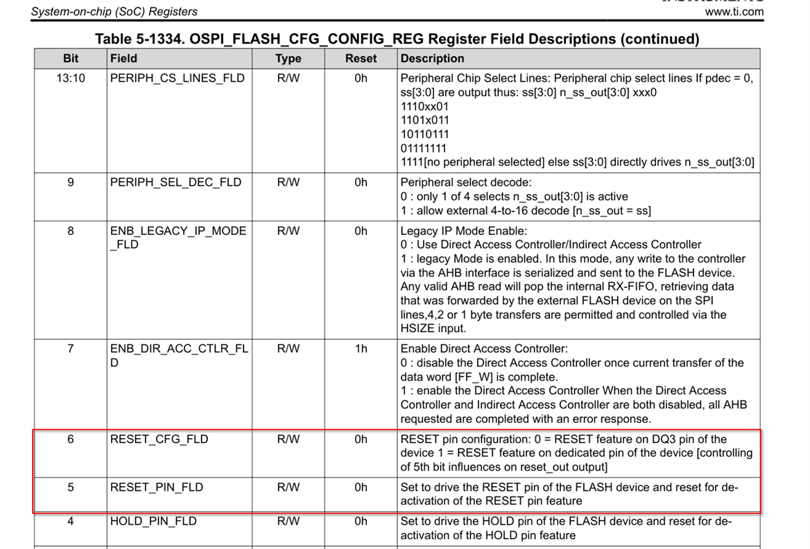
    This is enabled and disabled using the below bitfields in OSPI_FLASH_CFG register


    OSPI0_ZCZ_F_RESET_OUT0  signal is internally connect from MCU die to flash reset pin internally inside package. (in SIP package ZCZ_F). Warm_Reset is the additional reset source for OSPI Flash. 

    how to connect it to PORz.

    Apologies for the confusions in the statements on HW design guidelines and reference schematics (which has PORz shown as the reset source). PORz as additional reset source to flash is not completely correct.

    Warm_Reset is the prefered addon reset source for OSPI Flash (in ALL AM263Px packages).

    This is due to the below reason mentioned in Boot Chapter in TRM:


    FYI, present SDK always switches to 4-Byte addressing mode irrespective of size of flash. Warm_Reset or PORz is given as an additional source in order to take care of the above mentioned from ROM that flash should be reset before ROM accesses it. PORz is a cold reset. Warm reset can be triggered by user or can happen due to any other Warm_Reset sources (WDT, and resets sources mentioned in TRM).

    Every time PORz is asserted, Warm_reset will be asserted. Hence if we connect warm reset pin as a reset source to flash it by default takes care of PORZ, Software warmest trigger and other warm reset sources.

    Warm_reset is an Open-Drain pin that requires external pull-up resistor.

    Figure 8-1. of the datasheet SPRSP81D displays a 10k pullup on J3, so I was under the impression that J3 works as an active low input, like most reset inputs. But as I found out, the SDK code is setting the OSPI reset pin actively to high, making it impossible to trigger a reset by pulling it low externally.

    There is a small catch here. The RESET_PIN_FLD has reset value as 0 

    BIT[6:5]
    2'b10 - Dedicated reset line to flash enabled and flash out of reset (Reset line to flash is HIGH)
    2'b11 - Dedicated reset line to flash enabled and flash in reset (Reset line to flash is LOW)

    So to assert reset to flash a bit transitions are 10->11->10


    Thanks & Regards,
    Rijohn

  • thank you for your reply. I didnt have time to test further yet, but I will eventually.