This thread has been locked.

If you have a related question, please click the "Ask a related question" button in the top right corner. The newly created question will be automatically linked to this question.

MSPM0G1106: Questions about the SDK BSL UART code example

Part Number: MSPM0G1106

Hi team,

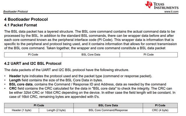
I'm currently looking into the following BSL example code. Can someone explain the reasoning behind setting the BSL TX/RX buffer sizes to "MAX_PACKET_SIZE + 2"? To be more specific, I'd like to understand why 2 is added to the MAX_PACKET_SIZE".


image.png


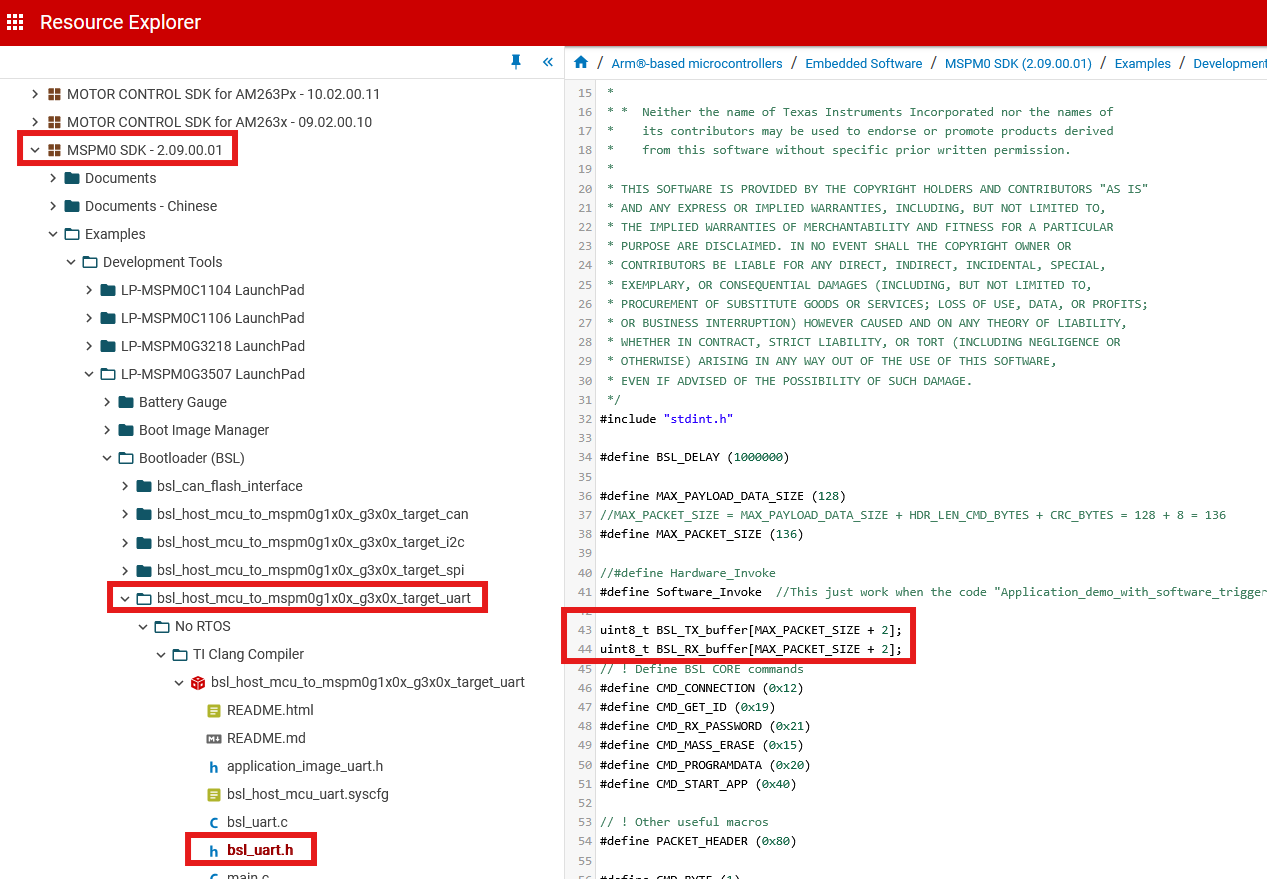
Also, is the following definition for MAX_PACKET_SIZE correct?

For example, to accommodate the Program Data message, the max packet size also need to have the room for 4-byte-address field which seems to be missing in the above mentioned comment.

From a different angle, what fields exactly does the 'PAYLOAD_DATA' in the MAX_PAYLOAD_DATA_SIZE' include?

Thank you,

Kyungjae Lee

  • Hello Kyungjae,

    I think this section clarifies what is BSL Core data and what is "PI Code".  So, I think it should technically be 128 + 7 bytes.  (3 bytes for Header and length, and 4 bytes for CRC) 

    CMD, ADD, and DATA see to all be considered payload data.

    I'm not sure why the additional +2 was added when defining the buffers.  I'd have to dig into the example more to see if the host code just happens to use extra bytes for it self.  .    

    Thanks,

    JD