This thread has been locked.

If you have a related question, please click the "Ask a related question" button in the top right corner. The newly created question will be automatically linked to this question.

AM263P4: AM263Px-CC evm board FSI communication

Part Number: AM263P4

Hello. I'm currently testing board-to-board FSI communication using two am263px-cc evm boards.
The basic example uses the fsi_hld_loopback_interrupt example to communicate between the boards.
I'm connecting the boards using a custom 10-pin cable, and I'm testing without the 10th pin (V3Y3_3V3_LDO1) on the cable.
I understand that the mux setting for am263px FSI is set to FSI by default, so I didn't configure a mux in the project. However, when performing FSI communication between boards, the internal loopback succeeds, but the external board-to-board c ommunication fails. What's the problem?
Additionally, the example uses interrupts, but in reality, I used polling. This is because an error occurred when using interrupts.

I've attached my example files below. Thank you.

fsi_hld_board_A.zip 

fsi_hld_board_B.zip

  • Hi Jinwoo,

    Have you probed the pins to see if signals are propagating to the pin and through the connection wire?

    Do you have a pin connection diagram that can be referred to in order to understand the external connectivity?

    What was the error that occurred when attempting to use the interrupts?

    Best Regards,

    Zackary Fleenor

  • I haven't tested the pins. Also, while error messages in the interrupt and polling mode codes weren't output, when I actually connected, I couldn't send or receive data. For reference on external connection methods, I referred to the AM263Px Control Card Evaluation Module User's Guide and the AM263Px SitaraTm Microcontrollers with Optional Flash-in-Package, PROC159B schematic file.
    Thank you.

  • Hi Jinwoo,

    Can you please perform these tests to provide us with more information on what may be happening?

    Best Regards,

    Zackary Fleenor

  • I tested the inter-board communication, but found no communication. So, I used an oscilloscope to check if the TXCLK and DATA0 waveforms were visible on only one board. Upon inspection, I found that the CLK and DATA0 waveforms were not visible, and the frequency was significantly lower than the previously set frequency of 40MHz.
    Thank you.

  • Hi Jinwoo,

    Are you able to provide scopeshots showing the signals?

    Can you provide a pin/signal diagram for the 10-pin cable being used to connect the two boards?

    Best Regards,

    Zackary Fleenor

  • Sorry, I can't provide a picture of the scope at the moment. Also, I made the 10-pin cable by crossing the TX and RX pins. Looking at other related questions, it seems like you're using a pmic and io expander to configure the LDO and pinmux. Is this necessary for FSI communication between boards?

  • Hi Jinwoo,

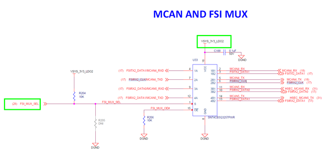
    You need to enable the LDO2 output from the PMIC in order to enable the correct on-board signal routing for the FSI interface.

    There are two dependencies on the LDO2 output being enabled:

    1. Powering the MUX for routing the FSI signals
    2. Pull-up resistor on the MUX SELECT net 

    LDO2 is enabled via SPI commands from the AM263P4 to the PMIC. 

    Refer to the PMIC User Register Configuration Example at examples/drivers/pmic/pmic_user_reg_cfg in the AM263Px SDK.

    Regards,

    Brennan

  • Hi, Brennan
    I've now solved the problem of transmitting and receiving between boards. Thank you.
    
    I have another question. As far as I know, FSI can transmit and receive in both directions simultaneously.
    However, I've encountered an issue where simultaneous transmission and reception between two boards causes failure. 
    Previously, successful tests were performed using ping-pong.

    Thank you.

  • Jinwoo,

    FSI uses separate, independent TX and RX modules. Each direction requires its own independent link:
    Board A                                      Board B
    FSI TX0 ----> TXCLK/TXD ----> FSI RX0
    FSI RX0 <---- TXCLK/TXD <---- FSI TX0

    The RX module is always clocked by the remote TX's clock (source-synchronous protocol), so the two directions are
    completely independent links.

    Common Causes of Bidirectional Failure

    1. Missing Flush Sequence - The most likely cause. Each RX module must receive a flush sequence from the remote TX to come out of reset:
      FSI_executeTxFlushSequence(txBase, prescalar);
    2. Initialization Order - Both boards must complete this sequence:
      - Initialize TX module
      - Initialize RX module
      - Send flush from TX to bring remote RX out of reset
      - Wait for flush from remote TX before attempting to receive
    3. Configuration Mismatch - TX and RX must have matching frame size and data width settings

    Recommended Initialization for Board-to-Board

    // Both boards: Initialize TX and RX
    FSI_performTxInitialization(txBase, prescalar);
    FSI_performRxInitialization(rxBase);

    // Both boards: Send flush to bring remote RX out of reset
    FSI_executeTxFlushSequence(txBase, prescalar);

    // Add synchronization delay or handshake here
    // Now both directions can operate "simultaneously"

    No Hardware Flow Control

    FSI has no built-in handshaking for simultaneous bidirectional transfers. The application must coordinate using:
    - Interrupt-driven operation
    - Frame tags for sequencing
    - Ping watchdog for link health

    Regards,

    Brennan