This thread has been locked.

If you have a related question, please click the "Ask a related question" button in the top right corner. The newly created question will be automatically linked to this question.

MSPM0G3507: Continuous ADC Sampling with DMA transfer

Part Number: MSPM0G3507

Hi TI team,

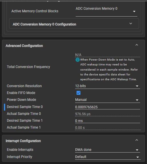
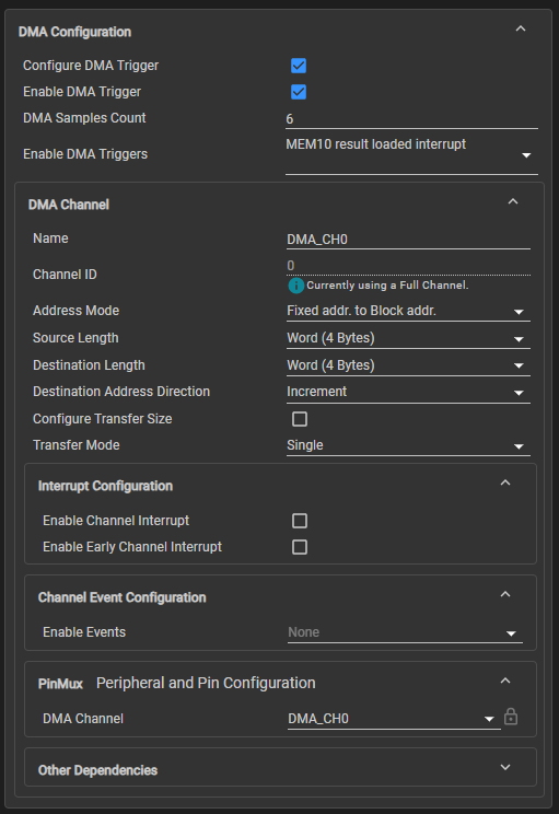
I try to do a Continuous ADC Sampling with DMA transfer. I need 1024 samples/s. The Sample Time 0 is set to 976.56us (1/1024). As example I modified the adc12_max_freq_dma. The conversion started only once. But with the setting 'Enable Repeat Mode' it should restart. What is the reason for this?

#include "ti_msp_dl_config.h"

#define ADC_SAMPLE_SIZE (1024)
/* When FIFO is enabled 2 samples are compacted in a single word */
#define ADC_FIFO_SAMPLES (ADC_SAMPLE_SIZE >> 1)

uint16_t gADCSamples[ADC_SAMPLE_SIZE];
volatile bool gCheckADC;

int main(void)
{
    SYSCFG_DL_init();

    /* Configure DMA source, destination and size */
    DL_DMA_setSrcAddr(DMA, DMA_CH0_CHAN_ID,
        (uint32_t) DL_ADC12_getFIFOAddress(ADC12_0_INST));

    DL_DMA_setDestAddr(DMA, DMA_CH0_CHAN_ID, (uint32_t) &gADCSamples[0]);
    DL_DMA_setTransferSize(DMA, DMA_CH0_CHAN_ID, ADC_FIFO_SAMPLES);

    DL_DMA_enableChannel(DMA, DMA_CH0_CHAN_ID);

    /* Setup interrupts on device */
    NVIC_EnableIRQ(ADC12_0_INST_INT_IRQN);

    gCheckADC = false;

    DL_ADC12_startConversion(ADC12_0_INST);

    while (1) {

        while (false == gCheckADC) {
            __WFE();
        }
        gCheckADC = false;
        DL_GPIO_togglePins(GPIO_LEDS_PORT, GPIO_LEDS_USER_LED_1_PIN);
        delay_cycles(1600000); 
        DL_GPIO_togglePins(GPIO_LEDS_PORT, GPIO_LEDS_USER_LED_1_PIN);
    }
}

void ADC12_0_INST_IRQHandler(void)
{
    switch (DL_ADC12_getPendingInterrupt(ADC12_0_INST)) {
        case DL_ADC12_IIDX_DMA_DONE:
            gCheckADC = true;
            DL_DMA_enableChannel(DMA, DMA_CH0_CHAN_ID);
            DL_ADC12_enableConversions(ADC12_0_INST); 
            break;
        default:
            break;
    }
}

image.pngimage.pngimage.png

  • Make sure the trigger will automatically step ... is selected.

    1024/6 = 170...4, you will get 4 ADC result left in ADC FIFO when 1020 result finished.

    Recommend to set ADC sample count to 5

  • yes it is


    And 1024/16=64
    Is there any disadvantage?

  • And 1024/16=64
    Is there any disadvantage?

    No, there is no 32 * 16 bit memory in ADC, so you can set such large value in DMA sample count.

    It's better to set DMA sample count = 1, and enable 1,3,5,7,9,11's MEM trigger (trigger DMA to transfer every two ADC result)

    Or

    It's better to set DMA sample count = 2, and enable 3,7,11's MEM trigger (trigger DMA to transfer every 4 ADC result)

  • If I understand this, 12 samples can be saved in the ADC memory.

    But why isn't the sampling continuing?

  • Hi, thanks for this example. I have some questions to understand it. Please correct my statements if they are wrong.

    - Sample Time 0 and 1 is set to 40us which results at 32MHz clock to a CCR value of 1280.
    - I think only sample time 0 is necessary
    - every 1280 clock cycles 1 ADC sample is aquired
    - Interrupt DL_ADC12_IIDX_DMA_DONE occurs if 1024 samples are aquired and saved in user variable gADCSamples

    - is this necessary and why 6? Is this the DMA Memory which size of 12 elements?

    // Clear ADC FIFO Data
    for(int i = 0; i < 6; i++) {
    DL_ADC12_getFIFOData(ADC12_0_INST);
    }


    - ADCGroupCount only stops the code after 10x1024 samples, no other sense (?)
    - Delay Cycles between the groups - why?
    - Implementation TimerA? Sample time 0 has a ccr of 1280 and not 255. What is the sense of TimerA?

  • - I think only sample time 0 is necessary

    I only use this sample time 0, 1 is not in use.

    - every 1280 clock cycles 1 ADC sample is aquired

    No, use timer to trigger ADC to start, ADC samples for 40us, then conversion.

    - Interrupt DL_ADC12_IIDX_DMA_DONE occurs if 1024 samples are aquired and saved in user variable gADCSamples

    Yes.

    - is this necessary and why 6? Is this the DMA Memory which size of 12 elements?

    Please remove this part of for loop code, this is my previous debug code to clear the ADC fifo.

    - ADCGroupCount only stops the code after 10x1024 samples, no other sense (?)

    You can stop at any ADC groups, 10 is my debug setting.

    - Delay Cycles between the groups - why?

    You can delete it.

    - Implementation TimerA? Sample time 0 has a ccr of 1280 and not 255. What is the sense of TimerA?

    use timer to trigger ADC to start, ADC samples for 40us, then conversion.

    Event is used between ADC and timer.

  • What settings I need with your example to get 1024 samples per second?

  • No change.

    I already set my code sampling rate = 1024 SPS.

    You can test it with some GPIO toggle in free run mode.

    Next following week is Chinese New year, if there is urgent support need, please submit a new ticket.

  • Ok, but for understanding:

    - for 1024S/s I need a sample rate of (1/1024)s=976.5625us not 40us?

    - Sample time 0 ist 1280 (40us at 32MHz), why not 31250 (1/1024 / 1/32MHz) for Sample time 0 ?

    - And why 255 for Timer 0? Timer 0 has in your example initial value of 1280...

  • And which ADC Channel and Pin is used. I recognize an ADC1 setting. But which pin I can connect for signal input tests? There isn't a pin selection.

  • nonono, I am using timer 1024hz

     to trigger ADC.

    You can select ADC input in ADC memory

    Input mix info can get from datasheet chapter 8 ADC section

  • Upload another fully modified code example for your test:

    4011.adc12_timer_single_DMA_G3507.zip

    https://e2e.ti.com/cfs-file/__key/communityserver-discussions-components-files/908/Session-0.sal

    Using PB12 toggle as a 1s DMA done indicator.

    Details requirement of this project and function recommendation is send to your local support team, please try to contact them for more information.

  • The sampling now looks good I think.

    Further I need the sampling with 1024 Samples/s and an DMA buffer of 2048. After first half of 1024 Samples are ready, the results can be used for final calculation, DMA can write instead results to the second half of DMA...

    It should work with early DMA Interrupt. But it only catches the DMA Done IRQ.

    void ADC12_0_INST_IRQHandler(void)
    {
        switch (DL_ADC12_getPendingInterrupt(ADC12_0_INST)) {
            case DL_ADC12_IIDX_DMA_DONE:
                gCheckADC = true;
                puts("DL_ADC12_IIDX_DMA_DONE");
                break;
            default:
                break;
        }
    }
    
    void DMA_IRQHandler(void)
    {
        switch (DL_DMA_getPendingInterrupt(DMA)) {
            case DL_DMA_EVENT_IIDX_DMACH0:
                puts("DL_DMA_EVENT_IIDX_DMACH0");
                break;
            case DL_DMA_FULL_CH_EVENT_IIDX_EARLY_IRQ_DMACH0:
                puts("DL_DMA_FULL_CH_EVENT_IIDX_EARLY_IRQ_DMACH0");
                break;
            default:
                break;
        }
    }
  • Do you enable DMA's NVIC?

    NVIC_EnableIRQ(DMA_INT_IRQn);

    This interrupt can be disable, if you enabled ADC DMA done, use one of two is OK/.

  • Ok with enable this, I can cath the IRQ.

    NVIC_EnableIRQ(DMA_INT_IRQn);

    DL_ADC12_IIDX_DMA_DONE and DL_DMA_EVENT_IIDX_DMACH0 are both full dma?

    But when IRQ DL_DMA_FULL_CH_EVENT_IIDX_EARLY_IRQ_DMACH0 appears I have full DMA with 2048 values (First loop array should have zeros at index 1024...2047). I need this IRQ at 2048/2.

  • DL_ADC12_IIDX_DMA_DONE and DL_DMA_EVENT_IIDX_DMACH0 are both full dma?

    Full/Basic DMA channel is a channel feature, channel 0 is a full DMA.

    Datasheet www.ti.com/.../slasex6c.pdf 8.5 DMA

    Both interrupts are DMASZ = 0 triggers.

    But when IRQ DL_DMA_FULL_CH_EVENT_IIDX_EARLY_IRQ_DMACH0 appears I have full DMA with 2048 values (First loop array should have zeros at index 1024...2047). I need this IRQ at 2048/2.

    Seems this config is correct:

    You can set a longer Timer trigger time, and you can see the early int is triggered at half size.

    Longer !

    Monitor this one:

  • Longer, why? 1024 S/s --> 976.5625us

    How can I monitor the DMA_DMACHAN... ? 

  • Maybe because ADC Timer DMA continues while debug stops... Ok then I understand your suggestion.

  • Longer, why? 1024 S/s --> 976.5625us

    I am using a timer to control ADC sampling rate.

    How can I monitor the DMA_DMACHAN... ? 

    In debug mode, register view, enable refresh

    Maybe because ADC Timer DMA continues while debug stops... Ok then I understand your suggestion.

    Yes, the key point is we are using timer to control ADC, but I tried to stop timer, it won't work, but I didn't further debug it.