MSPM0L2228: NONMAIN contents corrupted

Part Number: MSPM0L2228

Hi, 


During a development of a software for MSPM0L2228, CCS said that "NONMAIN contents corrupted" as you can see a picture below.

Could you tell me the reason of the error, and counter-measures for this issue???

2026-02-12-10-36.png


1) Build a software configured as below.

image.png

image.png

image.png


image.png


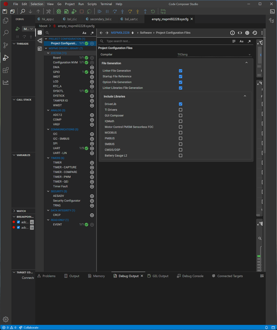
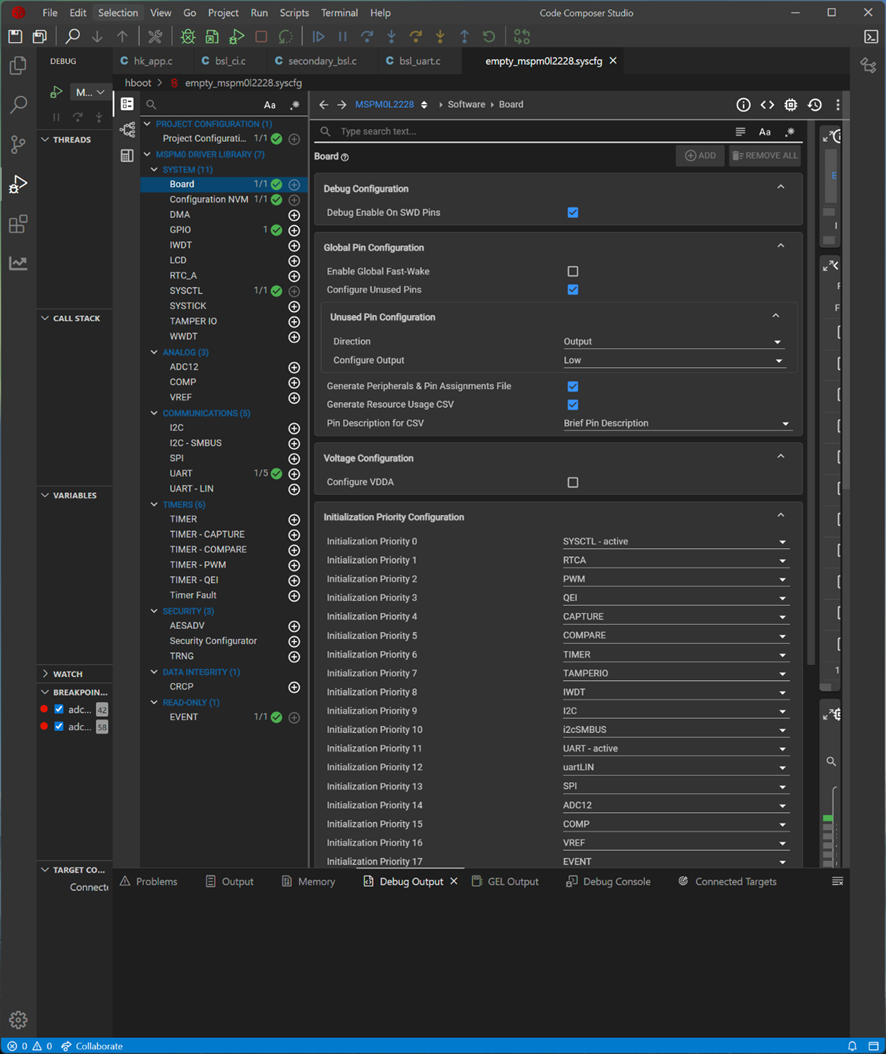
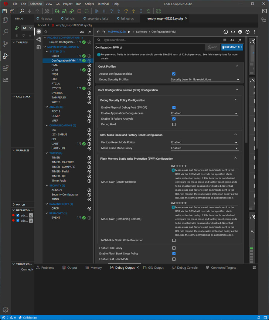
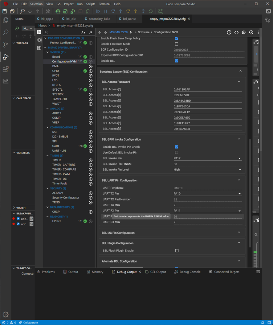
2) Uploaded it to our original PCB w MSPM0.

3) Power OFF and ON.

4) Checked the behaivar of my software.

5) Changed the logic of my software to fit what i wanna do.

6) Uploaded it to our original PCB again.

7) The error message like below apeared on CCS.


Best Regards, 

Susumu

  • Usually caused by incorrect operation in CCS, or nonmain region erased but not got programmed.

    Please try to follow the docs: https://www.ti.com/lit/pdf/slaaeo4

    Make sure that your operation is all follow the correct way.

  • All operation is same as the doc above.

    What is the reason of the phenomena above???

    Do you have any ideas to resolve it???

  • Do you have any ideas to resolve it???

    Not exactly.

    What is the reason of the phenomena above???
    Usually caused by incorrect operation in CCS, or nonmain region erased but not got programmed.

    Firstly, make sure that syscfg generated structure and compiled firmware is correct.

    Try to download it with nonmain flash erase enabled.

    If all operation follows the docs, it shouldn't be error.

    Next following week is Chinese New year, if there is urgent support need, please submit a new ticket.

  • Firstly, make sure that syscfg generated structure and compiled firmware is correct.

    Try to download it with nonmain flash erase enabled.

    If all operation follows the docs, it shouldn't be error.

    Could you find anything wrong from my comments above???. I described the operations in detail with 7 steps that caused this phenomena.

    If you can't, please forward this question to other engineer of TI.

  • No

    you operation step didn't include the details of CCS operation.

    And make sure that you are using the correct part number config in syscfg

  • Thank you for your info. I understood you need the part number.

    Attached please find the syscfg file.

    Please let me know if you find anything related to resolve this issue.

    And would you tell me the following understandings are correct or not.

    I guess I miss-understand some specifications of MSPM0 ucom.


    1) BCR exists on the ROM of MSPM0 ucom.

    => Yes or No

    2) BCR configuration exists on the flash memory of MSPM0 ucom.

    => Yes or No

    3) 1st and 2nd BSL exists on the flash memory of MSPM0 ucom.

    => Yes or No

    4) BSL configuration exists on the flash memory of MSPM0 ucom.

    => Yes or No

    5) The components above on the flash memory can be modified by developer.

    => Yes or No

    6) "NONMAIN area" means BCR Config, BSL Config, and 1st/2nd BSL.

    => Yes or No

    7) Only one CRC value is used for the whole area of the flash memory of MSPM0 ucom including BCR Config, BSL Config, and 1st/2nd BSL.

    => Yes or No

    8) The whole boot process of MSPM0 does NOT work if the CRC check was failed.

    => Yes or No

    9) Factory reset is available only if the setting of the BCR configuration is "true".

    => Yes or No

    10) The CRC process can NOT be disabled even only for development process and temporarily.

    => Yes or No

    11) The CRC process might be failed if the programming of the flash memory was failed by noise, wrong operation, and power disturbance etc.

    => Yes or No

    12) The CRC value should be re-calculated even if only 2nd BSL was modified but BCR Config, BSL Config were the same before.

    => Yes or No

    13) The CRC value exists on the flash memory of MSPM0 ucom.

    => Yes or No

    14) The CRC value might be damaged if the programming of 2nd BSL was failed.

    => Yes or No

    /**
     * These arguments were used when this file was generated. They will be automatically applied on subsequent loads
     * via the GUI or CLI. Run CLI with '--help' for additional information on how to override these arguments.
     * @cliArgs --device "MSPM0L222X" --part "Default" --package "LQFP-64(PM)" --product "mspm0_sdk@2.09.00.00"
     * @v2CliArgs --device "MSPM0L2228" --package "LQFP-64(PM)" --product "mspm0_sdk@2.09.00.00"
     * @versions {"tool":"1.25.0+4268"}
     */
    
    /**
     * Import the modules used in this configuration.
     */
    const Board         = scripting.addModule("/ti/driverlib/Board");
    const GPIO          = scripting.addModule("/ti/driverlib/GPIO", {}, false);
    const GPIO1         = GPIO.addInstance();
    const NONMAIN       = scripting.addModule("/ti/driverlib/NONMAIN");
    const SYSCTL        = scripting.addModule("/ti/driverlib/SYSCTL");
    const UART          = scripting.addModule("/ti/driverlib/UART", {}, false);
    const UART1         = UART.addInstance();
    const ProjectConfig = scripting.addModule("/ti/project_config/ProjectConfig");
    
    /**
     * Write custom configuration values to the imported modules.
     */
    Board.configureUnused             = true;
    Board.genPeriphPinFile            = true;
    Board.genResourceCSV              = true;
    Board.peripheral.$assign          = "DEBUGSS";
    Board.peripheral.swclkPin.$assign = "PA20";
    Board.peripheral.swdioPin.$assign = "PA19";
    Board.genFileMod.$name            = "ti_driverlib_BoardPins0";
    Board.genFileCSV.$name            = "ti_driverlib_ResourcesCSV0";
    
    GPIO1.$name                   = "GPIO_GRP_0";
    GPIO1.associatedPins[0].$name = "GPIO_TEST_OUT";
    
    NONMAIN.nonmainWarning      = true;
    NONMAIN.flashBankSwap       = true;
    NONMAIN.bslDefaultInvokePin = false;
    NONMAIN.bslInvokePinLevel   = 1;
    NONMAIN.bslAltConfig        = true;
    NONMAIN.bslAppVersion       = 0x1;
    NONMAIN.bslAltAddress       = 0x2023;
    NONMAIN.bslInvokePin        = "PA12";
    
    SYSCTL.SYSOSC_Freq        = 4000000;
    SYSCTL.HFCLKSource        = "HFXT";
    SYSCTL.peripheral.$assign = "SYSCTL";
    
    UART1.$name                    = "UART_0";
    UART1.enableFIFO               = true;
    UART1.enabledInterrupts        = ["BREAK_ERROR","FRAMING_ERROR","NOISE_ERROR","OVERRUN_ERROR","PARITY_ERROR","RX","RX_TIMEOUT_ERROR"];
    UART1.peripheral.$assign       = "UART0";
    UART1.peripheral.rxPin.$assign = "PA11";
    UART1.peripheral.txPin.$assign = "PA10";
    UART1.txPinConfig.$name        = "ti_driverlib_gpio_GPIOPinGeneric0";
    UART1.rxPinConfig.$name        = "ti_driverlib_gpio_GPIOPinGeneric1";
    
    ProjectConfig.migrationCondition = true;
    
    /**
     * Pinmux solution for unlocked pins/peripherals. This ensures that minor changes to the automatic solver in a future
     * version of the tool will not impact the pinmux you originally saw.  These lines can be completely deleted in order to
     * re-solve from scratch.
     */
    GPIO1.associatedPins[0].pin.$suggestSolution = "PB13";
    

  • 1) BCR exists on the ROM of MSPM0 ucom.

    BCR code is run before reset handler, and in the ROM.

    2) BCR configuration exists on the flash memory of MSPM0 ucom.

    BCR cfg is in the nonmain Flash.

    3) 1st and 2nd BSL exists on the flash memory of MSPM0 ucom.

    Default BSL is in ROM, secondary BSL is user BSL based on BSL invoke, saved in main Flash.

    4) BSL configuration exists on the flash memory of MSPM0 ucom.

    In the nonmain, behind the BCR.

    5) The components above on the flash memory can be modified by developer.

    Nonmain Flash can.

    6) "NONMAIN area" means BCR Config, BSL Config, and 1st/2nd BSL.

    refer to 1.4 Boot Configuration in TRM https://www.ti.com/lit/pdf/slau847

    or


    refer to https://www.ti.com/lit/ug/slaaeo4/slaaeo4.pdf

    nonmain only contain BCR/BSL configurations. no BSL code.

    7) Only one CRC value is used for the whole area of the flash memory of MSPM0 ucom including BCR Config, BSL Config, and 1st/2nd BSL.

    Two, for BCR and BSL cfg.

    8) The whole boot process of MSPM0 does NOT work if the CRC check was failed.

    Will stuck at ROM boot code, in this situation, M0 will locked permanently. nonmain CRC.

    9) Factory reset is available only if the setting of the BCR configuration is "true".

    FR will available when FR is enabled in nonmain-BCR

    10) The CRC process can NOT be disabled even only for development process and temporarily.

    Yes. I means nonmain CRC.

    11) The CRC process might be failed if the programming of the flash memory was failed by noise, wrong operation, and power disturbance etc.

    Nonmain CRC, yes.

    12) The CRC value should be re-calculated even if only 2nd BSL was modified but BCR Config, BSL Config were the same before.

    If you don't modify nonmain, no nonmain CRC need to be re-calculated.

    13) The CRC value exists on the flash memory of MSPM0 ucom.

    In tails of BCR/BSL in nonmain.

    14) The CRC value might be damaged if the programming of 2nd BSL was failed.

    No.

    2nd BSL is in main Flash.

    CRC of nonmain is in nonmain Flash.

    -------------------------------

    As long as you are using syscfg to generate the nonmain, CRC in the firmware won't be uncorrect.

    Since you are using nonmain modification + 2nd BSL, you need to modify the nonmain for 2nd BSL address.

    Based on the 2nd BSL demo, I didn't see any issue of programming.

    Only issue is that if addr=0x0 is empty, and you only programed 2ns BSL (Not start from 0x0), there will be error to indicate you after programming 2nd BSL demo. But this doesn't matter.

    Another thing you need to remember is :

    Enable nonmain erase only in the that project that contain nonmain region data. (Like you add NVM configuration in syscfg.)

    Don't enable nonmain erase in the project that only have user app code in main Flash.

  • ★Q1

    Enable nonmain erase only in the that project that contain nonmain region data. (Like you add NVM configuration in syscfg.)

    ==>
    Is it OK to program the same BCR cfg. and BSL cfg. again for each time after building modified 2nd BSL???
    If not, please tell me the reason.

    I just wanna know the reason that the message "NONMAIN contents corrupted" was shown on CCS.

    ★Q2

    13) The CRC value exists on the flash memory of MSPM0 ucom.

    In tails of BCR/BSL in nonmain.


    ==>No.
    "BCR" is NOT in nonmain but only in the ROM as you mentioned above.

    Do you mean "BCR cfg."???

    if so, it might be in the same sector of flash memory even though it is at tails of the flash,
    and it might be erased at the same time because flash memory should be erased only for each sector.

    Is there a risk that BCR cfg. and/or BSL cfg. would be erased at the same time if those exist at the same sector of BSL???


    ★Q3

    Only issue is that if addr=0x0 is empty, and you only programed 2ns BSL (Not start from 0x0), there will be error to indicate you after programming 2nd BSL demo.

    ==>
    What do you mean by "addr=0x0"??? Do you mean nonmain area???

    ★Q4:Improving Structure of TI Documentation

    We developer side currently have multiple documents with very similar content, and each of them exceeds 100 pages.
    This makes it quite difficult to manage and navigate the information efficiently.

    Could we consider restructuring these materials into a more efficient documentation framework???

    A more standardized and centralized document structure would greatly improve usability, maintainability, and overall efficiency.

    - Examples -

    Application Note MSPM0 Bootloader (BSL) Implementation
    SLAAE88C – MARCH 2024 – REVISED SEPTEMBER 2024

    =>31 pages

    User’s Guide MSPM0 Bootloader
    SLAU887 – FEBRUARY 2023

    =>32 pages

    Application Note MSPM0 Live Firmware Update (LFU) Bootloader Implementation
    SLAAEC9 – JULY 2023

    =>13 pages

    User's Guide MSPM0 NONMAIN Flash Memory Configuration Guide
    SLAAEO4 – NOVEMBER 2025

    =>47 pages

    ★Q5:Improving Terminology Consistency in TI Documentation

    The terminology used across the documents is inconsistent and confusing.
    For example, SLAU887 defines "Bootloader (BSL)" "Bootcode (BCR)" and their respective configuration structures in a specific way.

    However, SLAU847E describes "boot configuration routine (BCR)" and "bootstrap loader (BSL)" with different explanations of their roles and interactions.

    Furthermore, you and CSS introduces additional terms such as “Alternate BSL” and “2nd BSL” and so on without clearly aligning them with the other definitions.

    As a result, it is difficult to fully understand the architecture, and even within TI’s own documentation the terminology does not appear to be consistently defined.

    Could we consider restructuring terminology consistency???

    Thank you in advance, 

    Susumu