Part Number: AM263P4
Other Parts Discussed in Thread: TMDSCNCD263P
Hello.
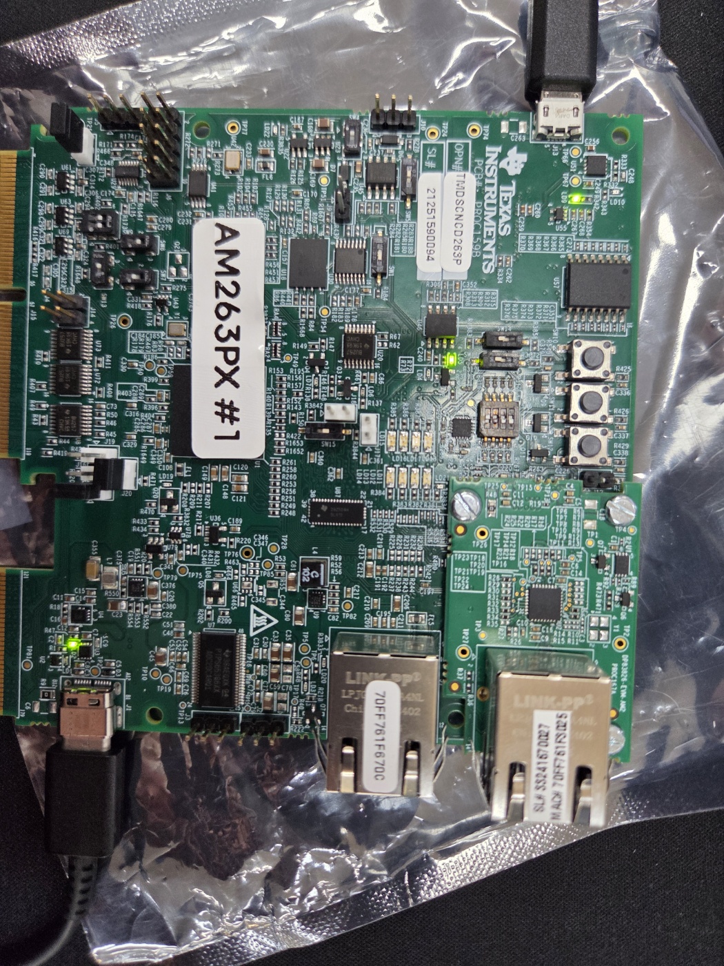
I have a question about debugging the AM263P control card.
The board was working fine, and I tried testing the FSI by connecting the FSI kit.
However, after powering it up, I encountered a problem. The connection to CCS also failed, and the following error message persists:
"XDS110 / CS_DAP_0 error -1170 (DAP not accessible)"
I'm currently using the AM263P4-CC (TMDSCNCD263P) EVM board.
I've set it to UART boot mode. I've also checked other boards, and the LD3 and LD4 LEDs are on.
- Current Symptoms
LD2 = On (12V input seems to be coming in)
LD3 = Off
LD4 = Off
LD5 = On
* There's almost no response when pressing the reset button.
* The target connection to CCS doesn't work at all.
I believe **the input power is coming in, but the PMIC sub-power (3.3V/1.2V) is not outputting.**
Here are the solutions I've tried:
1. Removed **all external connections**, including the FSI cable/adapter. 2.
Replaced the USB-C cable.
3. Replaced the power adapter/port and tested.
4. Unplugged the power cord completely, left it on for **over an hour**, and then plugged it back in.
5. I'm still experiencing the same issue (LD3/LD4 OFF, CCS disconnected).
The voltages I measured (relative to GND) are as follows:
- TP7 = approximately 3.7V
- TP8 = 0V
- TP16 / TP17 / TP18 = 0V
- BB6V on the C30 side was not detected.
Based on the schematic,
* TP7 appears to be BB_OUT / VCC_6V0_BBOUT.
* TP8 appears to be VREG.
TP7 is not a 6V series, but only outputs about 3.7V, and TP8 is 0V, so it's likely a PMIC failure to start up or a PMIC defect.
My questions are:
1. Is this symptom due to a damaged/failure to start up PMIC?
2. Or is it a short-circuit (overload) of the 3.3V/1.2V rails, triggering the PMIC protection mechanism?
3. I'm curious about a concrete solution to this situation (this is my primary concern).
4. What additional measurements would be helpful?
Thank you.
 .
.