This thread has been locked.

If you have a related question, please click the "Ask a related question" button in the top right corner. The newly created question will be automatically linked to this question.

LP-MSPM0G3507: LP-MSPM0G3507 NACK errors on the MCAN bus

Part Number: LP-MSPM0G3507
Other Parts Discussed in Thread: SYSCONFIG, , TCAN-SOIC8-EVM, MSPM0G3507

Hi,

I am currently working on a prototype that needs to communicate on a 500kbps classic CAN bus. All I need is to filter the messages on the bus for a certain ID and use that as a trigger for lighting.

I am basing the software on the single_message_rx example for the LP-MSPM0G3507. The Main() function is exactly the same as is the interrupt. The sysconfig clocking is exactly the same, as are all other options except that CAN FD is deselected, a 500 kbps bit rate is selected and the ID filters are disabled for troubleshooting.

The CAN transceiver I am using is the TCAN1057AVDRQ1 soldered onto the TCAN-SOIC8-EVM. The transceiver VCC comes from the 5V rail of the LP-MSPM0G3507 and the VIO comes from the 3.3V rail. I send CAN messages using busmaster through a USB to CAN IXXAT device. The terminations are correct as I measure 60ohms with a DMM on the bus.

I know the transceiver is working correctly as shown in the oscilloscope capture.

On the CAN_TX line there is only noise.

I have measured up to the IC pin (PA13 for CAN_RX) and I can see the CAN message is correct and well decoded by the oscilloscope. But the MSPM0G3507 never acknowledges the message, I never trigger the interrupt, basically the microcontroller stays in the low power state and never wakes up from _WFE().

I am a hardware guy with little software experience and would very much appreciate support on this issue as one of our projects hangs in the balance.

Thank you very much.

  • Please refer to this demo code:

    mcan_application_LP_MSPM0G3507_nortos_ticlang_20250801.zip

    You can modify the filter here, I set 4 filter in syscfg.

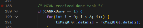
    You can get rx data here:

    And send tx here:

    For the hardware setup, please double check syscfg pin assignment.

  • I have just tried this code and still get NACK errors on every frame. I double checked the pin assignement in sysconfig (Rx = PA13 and TX = PA12) which is correct according to the launchpad user guide.

    I have tried it on a second launchpad and get the same errors.

    Am I to understand that the example code from mcan_message_rx in mspm0_sdk_2_09_00_01 is not functional?

    Also, please reply to my original request, I do not need filters nor TX right now. All I need is for the microcontroller to aknowledge the CAN frames that I am generating on the bus. mcan_message_rx should be the example to follow in this case no?


  • I have just tried this code and still get NACK errors on every frame.

    NACK means there is no other CAN node on CAN bus, only the sender itself, emmmmmm, just need to confirm your CAN bus signal is connected to M0 CAN controller via the CAN transiver.

    Am I to understand that the example code from mcan_message_rx in mspm0_sdk_2_09_00_01 is not functional?

    All the can demo in SDK should be functional. I didn't see any issue on that.

    I do not need filters nor TX right now.

    Both filter or Tx won't influence the ACK signal, all can controller need to ACK any CAN frame.

    mcan_message_rx should be the example to follow in this case no?

    Yes, it's enough.

  • This is how I am set up, using the SOIC8 TCAN devkit and the LP-MSPM0G3507.


    This setup is taken directly from the MSPM0G hardware developement guide. 

    RXD is connected to PA13, TXD is connected to PA12.

    As you can see in the image of my original request, the CAN transceiver is working as expected and generating 3.3V CAN messages from the messages sent on the CAN_H and CAN_L bus.

  • As you can see in the image of my original request, the CAN transceiver is working as expected and generating 3.3V CAN messages from the messages sent on the CAN_H and CAN_L bus.

    That seems ok for me.

    And based on your previous NACK error, that means MSPM0 is not on a CAN bus yet or MSPM0 CAN controller is not inited successfully.

    Here is my suggestion:

    a CAN send test at M0 side will make sure that your hardware setup is OK, since can send won't be difficult at M0 side.

    You can directly monitor CAN bus using your CAN analyzer.

    This is the easiest way to confirm the CAN bus is OK.

    Then you can further debug your Rx function.

    Since this demo mcan_message_rx will only support one time CAN Rx, please pay attention to yout send timing.

    I understand that you only want a CAN rx function, but trust me, this is easy to use:

    mcan_application_LP_MSPM0G3507_nortos_ticlang_20250801.zip

    -------------

    Also, need to make sure that there is no logic level issue when you connect STB to 5V, but other logic level RXD/TXD is 3.3V.

  • Hi,

    I have just tried to do a CAN tx test using the demo mcan_single_message_tx. It is not working at all, I see nothing coming into the CAN analyzer.

    The things that I have modified in the demo are:

    - CAN FD disabled

    - Arbitration bit rate and data bit rate set to 500kbps

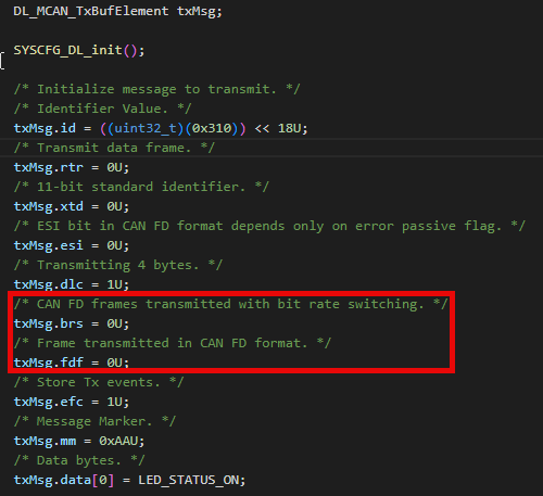
    - The TxBufElement is modified to be a Can classic message as follows

    "Also, need to make sure that there is no logic level issue when you connect STB to 5V, but other logic level RXD/TXD is 3.3V."


    I have tried to tie STB to VIO(3.3V) and VCC(5V) and get the same results, nothing.

    I am using PA12 as the TX pin, connected to the TX pin of the TCAN device, and PA13 as the RX pin, connected to the RX pin of the TCAN device.

    I am at a complete loss as how to make this work as I am using two devkits and example software, I don't even understand where it could fail...


  • I have also tried the same test setup with two different LP-MSPM0G3507 devkits and get the same results, so I don't beleive it is a hardware fault. The TCAN seems to be working fine as it decodes messages sent from the IXAAT usb to CAN converter with no issues.

    Here are the Init and Config parameters used during intialization, do you see any errors on this side?

    static const DL_MCAN_InitParams gMCAN0InitParams= {
    
    /* Initialize MCAN Init parameters.    */
        .fdMode            = false,
        .brsEnable         = false,
        .txpEnable         = false,
        .efbi              = false,
        .pxhddisable       = false,
        .darEnable         = false,
        .wkupReqEnable     = true,
        .autoWkupEnable    = true,
        .emulationEnable   = true,
        .tdcEnable         = true,
        .wdcPreload        = 255,
    
    /* Transmitter Delay Compensation parameters. */
        .tdcConfig.tdcf    = 10,
        .tdcConfig.tdco    = 6,
    };
    
    static const DL_MCAN_ConfigParams gMCAN0ConfigParams={
        /* Initialize MCAN Config parameters. */
        .monEnable         = false,
        .asmEnable         = false,
        .tsPrescalar       = 15,
        .tsSelect          = 0,
        .timeoutSelect     = DL_MCAN_TIMEOUT_SELECT_CONT,
        .timeoutPreload    = 65535,
        .timeoutCntEnable  = false,
        .filterConfig.rrfs = true,
        .filterConfig.rrfe = true,
        .filterConfig.anfe = 1,
        .filterConfig.anfs = 1,
    };
  • No issue seen at my side.

    - The TxBufElement is modified to be a Can classic message as follows

    No issue.

    I am using PA12 as the TX pin, connected to the TX pin of the TCAN device, and PA13 as the RX pin, connected to the RX pin of the TCAN device.

    Correct.

    Make sure you assign these two pins in syscfg pinmux in mcan.

    Here are the Init and Config parameters used during intialization, do you see any errors on this side?

    No issue seen here.

  • Are you running the single_message_tx example code? I see the ID is changing in your screenshot which the code does not do right?

    while in debug I can see using breakpoints that the interrupt for the PB is trigerred and that the transmit code is executed. Inspecting the txMsg structure i get the following (for CAN ID 0x04):

    {"id":1048576,

    "rtr":0,"xtd":0,

    "esi":0,"dlc":1,

    "brs":0,

    "fdf":0,

    "efc":1,

    "mm":170,

    "data":[0,0,0,0,0,0,0,0,0,0,0,0,0,0,0,0,0,0,0,0,0,0,0,0,0,0,0,0,0,0,0,0,0,0,0,0,0,0,0,0,0,0,0,0,0,0,0,0,255,255,255,255,255,255,255,255,255,255,255,255,31,10,0,0]}

    and still no output at all from the MSPM0.

    The pins are correctly assigned in sysConfig.


  • Make sure that you connect correct Tx-Tx, Rx-Rx between M0 and TCAN.

    If one setup is not work, try to switch them.

    If Tx and Rx is connected with wrong way, there won't be any signal on the Tx PIN.

    while in debug I can see using breakpoints that the interrupt for the PB is trigerred and that the transmit code is executed. Inspecting the txMsg structure i get the following (for CAN ID 0x04):

    This is only hthe RAM buffer, these data will write to CAN RAM for CAN core usage.

    Once CAN RAM is written, and Tx require is set, MCAN will send these data to Tx pin.

    Are you running the single_message_tx example code? I see the ID is changing in your screenshot which the code does not do right?

    Both [single_message_tx ] and [mcan_application] is test at  my side.

    For [single_message_tx], you need to push button to trigger can send, do you push the button?

  • After much testing I found out that my issue was due to pin 8 of the TCAN module set to Silent mode. I had the jumper J2 on the TCAN-SOIC8-EVM set to VCC when it should have been set to GND.

    Such a stupid mistake but in the end all works well now!

  • Glad to hear your issue resolved~ thanks for the feedback~