This thread has been locked.

If you have a related question, please click the "Ask a related question" button in the top right corner. The newly created question will be automatically linked to this question.

TMS570LS3137: Flash Emulated EEPROM writing behavior after corruption test

Part Number: TMS570LS3137

Hello,

In a context of FEE memory corruption testing, I am trying to change some byte value saved in FEE and check that our application at startup thanks to a CRC mechanisms can correctly detect the corrpution when reading the data saved.

Our application init code is indeed detecting the corrupted data, but trying to write back correct values here I have some stranges behaviors. We correctly initilialized the FEE with TI_Fee_Init(), before all of this.

It seems that the data inside the FEE cannot be (or partially) physically written properly, even if the code shows that we go to a wrting sequence and use FlashAPI F021 Write function.

image.png

Nevertheless, after some restarts, corruption still being detected, the data are finally properly written.

I do not understand the behavior in between as you can see hereafter in the green zone :

FEE Blocks.dat image.png

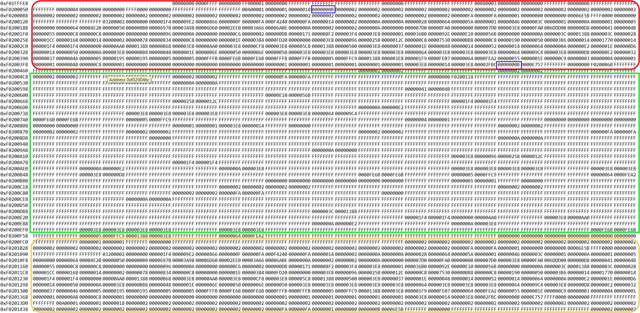
Above in the red zone, are the initial data flashed with 2 manually corrupted with Code Composer studio (in blue), then in between (green zone) with severals restart attempt seems that the write does work only partially, finally the yellow zone, one startup sequence managed to write properly the data in FEE.

In addition, please find here attached the dump of the FEE from address 0xF0200000.

Is there is maybe interferences with the debuger for my test ? Or something else.

Thank you,

Regards,

Marc

  • Hi Marc,

    Can you please tell me the number of virtual sectors, number of blocks, and size of each block? You know that at least 2 virtual sectors should be used. The size of one virtual sector should be > total size of all the data blocks (plus header).

  • Hi QJ Wang,

    Number of Virtual sector : 2 (each is 32Kb)

    number of block : 4

    Block 1 : 160 Bytes

    Block 2 : 800 Bytes

    Block 3 : 8 Bytes

    Block 4 : 8 Bytes


    In my test shown above, block 1 and 2 are manually (byte marked blue) corrupted using CCS and the SEGGER RTT debugger to flash the FEE address.

    Thank you for the support,

    Regards,

    Marc

  • Hi Marc,

    The FEE configuration looks ok. Which F021 flash is used your project?

    F021_API_CortexR4_BE_V3D16.lib should be used. F021_API_CortexR4_BE_L2FMC_V3D16.lib is for TMS570LC43x and RM57 only.

    I analyzed your data. Here is the summary of the data blocks in the FEE. I am sorry I am not able to upload the file. Will try later.

  • HI QJ,

    I confirm we are using F021_API_CortexR4_BE_V3D16.lib.

    Regards,

    Marc

  • HI QJ,

    Thank you for the analysis, I see that your tool parsed correctly the different 4 blocks, there is several points I do not understand :

    1) At 0xF0200450 address, according to the block header 0xFFFFFFFF 0x00000000 0xF0200060 0xFFFFFFFF 0xFFFFFFFF 0xFFFFFFFF, it seems to be a failed new attempt to write block 1 ( I see previous valid address 0xF0200060, match where was the block 1 with one voluntary corrupted value). We see afterwards some data which has been partially written, 

    0xF0200498: 0x00000002 0x00000002 **** Error: Corrupt Block --> block 1 data written
    0xF02004A0: 0xFFFFFFFF 0xFFFFFFFF Empty Block --> block 1 data not written
    0xF02004A8: 0xFFFFFFFF 0xFFFFFFFF Empty Block
    0xF02004B0: 0x00000002 0x00000002 **** Error: Corrupt Block
    0xF02004B8: 0xFFFFFFFF 0xFFFFFFFF Empty Block
    0xF02004C0: 0xFFFFFFFF 0xFFFFFFFF Empty Block

    Same at 0xF0200508:address, 0xF0200508: 0xFFFFFFFF 0x00000000 0xF0200118 0xFFFFFFFF 0xFFFFFFFF 0xFFFFFFFF, failed attempt to write block 2

    0xF0200520: 0xFFFFFFFF 0xFFFFFFFF Empty Block
    0xF0200528: 0xFFFFFFFF 0xFFFFFFFF Empty Block
    0xF0200530: 0xFFFFFFFF 0xFFFFFFFF Empty Block
    0xF0200538: 0xFFFFFFFF 0xFFFFFFFF Empty Block
    0xF0200540: 0xFFFFFFFF 0xFFFFFFFF Empty Block
    0xF0200548: 0x0000000A 0x0000000A **** Error: Corrupt Block
    0xF0200550: 0xFFFFFFFF 0xFFFFFFFF Empty Block
    0xF0200558: 0xFFFFFFFF 0xFFFFFFFF Empty Block

    2) At -0xF0200830 : 0xFFFFFFFF 0x00000000 0xFFFFFFFF 0xFFFFFFFF 0xFFFFFFFF 0xFFFFFFFF

            -0xF0200C00: 0xFFFFFFFF 0x00000000 0xFFFFFFFF 0xFFFFFFFF 0xFFFFFFFF 0xFFFFFFFF 

    seems to be a new block uninitialized.

    3) At 

    0xF0201088 : 0xFFFF0000 0x00000000 0xFFFFFFFF 0xFFFFFFFF 0xFFFFFFFF 0x03200002 block 2

    0xF02013C0: 0xFFFF0000 0x00000000 0xFFFFFFFF 0xFFFFFFFF 0xFFFFFFFF 0x00A00001  block1

    Blocks 1 & 2 have been copied here and now are marks as invalid

    But finally : 

    4) At

    0xF0202008: 0xFFFFFFFF 0x00000000 0xFFFFFFFF 0xFFFFFFFF 0xFFFFFFFF 0x00A00001 

    0xF02020C0: 0xFFFFFFFF 0x00000000 0xFFFFFFFF 0xFFFFFFFF 0xFFFFFFFF 0x03200002 

    Both blocks has been restored and marks as valid, without the corrupted byte introduced at first, which is the expected behavior.

    Overall I just do not unterstand the point 1), 2), 3), which correspond to system restart which shall have initiate the recovery and writes valid blocks as it is finally done at step 4).

    Maybe the test and corruption with CCS, triggers some disturbance with the FEE. I will try an other way maybe !

    Regards,

    Marc

  • You use a correct flash library.

  • Hi Marc,

    Please double check if the wait states for EEPROM has been set correctly. Per datasheet, the wait states at 160MHz system clock should be 3.

    It is configured by writing 0x3 to EWAIT filed of EEPROM_CONFIG register: 0xFFF8_72B8.

    The code is in system.c:

  • Hi QJ,

    Thank you for the feedback.

    I confirm to you that we have the indicated wait states for EEPROM in our project : 

    Overall, this corruption testing represents a robustness case that we would like to achieve. 

    Please come back to me in case of others though, how to check this.

    Thanks,

    Regards,

    Marc

  • Hi Marc,

    I am trying to change some byte value saved in FEE and check that our application at startup thanks to a CRC mechanisms can correctly detect the corrpution when reading the data saved.

    I assume that you changed the byte (flip the bit "1" to "0") of a valid data block manually using Flash API. If you changed the data, did you change the status (valid-->invalid) in the data block header.

    If you don't disrupt the data byte manually, does the FEE driver work properly? The EEPROM is also protected by ECC.

  • Hi QJ,

    I was indeed trying to flip some bits manually in the FEE blocks, to simulate a kind of corruption, not using Flash API but directly with code composer studio debug (giving a byte address with a new value to flash and triggering the flash using SEGGER flash probe and SW). Also I didn't want to change the blocks status to invalid, as my test corruption scenario would be just on byte or more the block data area.

    Regarding your questions :

    If you don't disrupt the data byte manually, does the FEE driver work properly? The EEPROM is also protected by ECC.

    --> In general the FEE driver works fine, just this manipulation with Code Composer studio leads to the presented above behavior.

    We do not activated the ECC on the EEPROM for our project if I am not wrong. So I am not sure this could have an impact.

    I will come back to you if I have further observations regarding my tests.

    Thank you !

    Regards,

    Marc

  • Ok, thank you!