This thread has been locked.

If you have a related question, please click the "Ask a related question" button in the top right corner. The newly created question will be automatically linked to this question.

AM6422: How to configure PRU GPIO pins

Part Number: AM6422
Other Parts Discussed in Thread: TMDS64EVM

I am trying to configure the AM6422 PRI_ICSSG GPIO pins to use MII_G_RT1, MII_G_RT2 and UART0 on a bare-metal setup.

On microcontrollers without the PRU-type subsystem, this is usually a straightforward process of setting the respective MUX setting, IN/OUT setting, etc in the pad config register for the targetted pins.

With the addition of the PRU, I am having trouble understanding what needs to be done. From reading the AM64x TRM, it appears that this is now a two-tiered process, but please correct me where I'm wrong:

1) To start, set the proper PADCONFIG register to select mux mode for the PRU (for instance, PADCONFIG11.MUXMODE = 2 for PRG0_RGMII1_TD0)

2) Next I need to set CSSG_GPCFG0_REG.PR1_PRU0_GP_MUX_SEL to "2" in order to configure the use of the MII mode signals, as specified in the 4th column of TRM table 6-51.

Is this correct? Or is the step 2 only needed with the PADCONFIG register in step 1 is generically used to configure the corresponding PRU0_GPO/GPI signals (mux mode = 0 or 1)?

If so, looking at figure 6-17, I am able to see the MII_G_RT1 signals PRG1_RGMII1_RD[3:0] under the "MII mode" column in table 6-51 (specifically on page 529) but am not able to find the other receive signals PRG1_RGMII1_RXC or PRG1_RGMII1_RX_CTL until I get down to the subsection "MII_G_RT1 (RGMII mode)" on page 532, but this seems to be a different thing than the listings for "alternate functions" at the beginning of the table.

And the final question as related to the PRU internal multiplexing, how do the above concepts above map to the idea of PRUn R30/R31 inputs and outputs? Does this impact how data is received or transmitted across that interface? 

Thanks!

  • Hello Seth,

    PRU internal multiplexing? 

    My understanding is that the PRU internal multiplexing is applied per-slice. So if slice0 is configured to use R30/R31 for PRU GPO/GPI, then you would not be able to access the MII signals from that slice. For more information, please start by reading this other thread:
    AM6442: PRU ICSSG internal mux e gpio mode 

    Let's talk about interacting with UART 

    If you are interacting with the hardware UART in the PRU subsystem, then the signals from the hardware UART do not go through the internal mux. They have their own signal path.

    HOWEVER, if you are implementing the UART in software, then you would need to make sure that the internal pinmux was set to 0 to bitbang the pins with the GPI/GPO signal, or 1 to use the 3 channel peripheral interface to implement UART. 

    Ok, but if I am doing Ethernet, do I interact with the MII and then that peripheral has a separate signal path, like the hardware UART? Or is the PRU directly interacting with the pins, which requires setting the internal multiplexing? 

    We are starting to get towards the edge of what my applications team can support on the forums (I specifically do not have any expertise in Ethernet networking firmware). I still categorize this pinmuxing question as a "general PRU question", but I will need to get input from the PRU firmware devs to comment.

    What can you expect going forward?

    I have notified your company's TI representative that you are interested in accessing the source code for the PRU Ethernet firmware. But I'll need you to give us permission to reach out to you directly, or I'll need you to reach out to them - I have been told they have been interacting with people in your company with initials JV and DG.

    We will be able to provide you the Ethernet source code, but we are not going to be able to answer questions about the source code.

    We can continue answering general PRU questions on the forums, but not questions specific to Ethernet. If you need firmware development support, there are some third parties that we can recommend who have done PRU Ethernet before. One of our teams is also starting to build out a paid support model for custom PRU Ethernet development - I do not know a lot about it, but if that is potentially interesting to yall I can check if it would make sense for your context, and provide you company's TI representative with more information.

    Regards,

    Nick

  • Hello again. You certainly have permission to reach out to me directly. I am eager to get my hands on something concrete I can use as a starting example. I look forward to hearing from your rep. If easier, please send me there contact info and I will initiate contact.

    I understand the fact that this forum may not be the appropriate place to get my Ethernet firmware questions answered, and appreciate that the application team is not designed to support it. But is there any other techincal support team/forum/etc that is accessible by TI customers? At the end of the day, I have a piece of hardware and a manual developed by TI, and questions on how to properly set registers to use it in a specific way, so hope there is someone who can answer those questions!

    Pivoting to my original question, when I read the link you sent me (AM6442: PRU ICSSG internal mux e gpio mode - Processors forum - Processors - TI E2E support forums), this is what I gether I need to do to set up my pin muxes for PRU to access MII as Ethernet controller, so please correct me if wrong:

    1) On the A53 core, configure the PADCONFIG settings for PADCONFIG46, PADCONFIG47, PADCONFIG48, etc to MuxMode = (PRG1_RGMII1_RD0-3, etc)

    2) On the PRU1 core, I set  ICSSG_GPCFG1_REG.PR1_PRU1_GP_MUX_SEL = 2 for MII Mode

    So in order to properly set the pinmux settings, I need the A53 PADCONFIG settings to align with the mode I select in the PRU GPCFG MUX selection. Is this the correct approach or am I still misunderstanding the steps needed?

    I have tried to attach an image of the end to end trace of these signals as provided in the TI TMDS64EVM board schematic, but am getting errors that are preventing the upload from succeeding. Basically I am trying to enable the PRU1 PRG1_RGMII1_[R*/T*] signals from schematic page 27 as they are routed through "ICSSG RGMII 1 Ethernet PHY" component on page 18 and through the associated RJ45 connector (my orignal post discussed PRU0, PRG0 RGMII signals, but my EVM does not support those signals for external RJ45 connection).

  • Here is the figure I tried updating earlier which shows at the top right the pins on the board am trying to select via muxing, continuing counterclockwise around the image the the connector on the EVM at the bottom right.

  • I suggest referencing the MCU+ SDK ENET ICSSG Examples:

    1. Study MCU+ SDK Examples:

      • Path: <SDK>/examples/networking/enet_layer2_icssg/
      • Look at pinmux configuration in ti_drivers_config.c or board configuration files
      • Check ti_board_open_close.c for ICSSG initialization sequence
    2. Correct Configuration Steps:

      Step 1: PADCONFIG (System Level)
      // Configure pads for PRU1 RGMII1 signals
      PADCONFIG46 = PRG1_RGMII1_RD0 (check TRM for exact mux mode value)
      PADCONFIG47 = PRG1_RGMII1_RD1
      // ... continue for all RGMII pins (RD[3:0], TD[3:0], RXC, TXC, RX_CTL, TX_CTL)

      Step 2: PRU Internal Mux (ICSSG Level)

      // For PRU1 Slice1, set to MII mode
      ICSSG_GPCFG1_REG.PR1_PRU1_GP_MUX_SEL = 2 // MII Mode
    3. Key Insights from MCU+ SDK:

      • Both steps are required: PADCONFIG routes signals to PRU subsystem; GPCFG routes them within PRU to MII hardware
      • RGMII vs MII: Table 6-51 shows both modes; ensure you're configuring for the correct mode (RGMII is more common)
      • Per-slice configuration: PRU0/PRU1 each have separate GPCFG registers
      • R30/R31 doesn't apply: When GP_MUX_SEL = 2 (MII mode), the MII_G_RT hardware handles signals directly; R30/R31 are for GPIO mode (GP_MUX_SEL = 0)
    4. Specific Files to Reference:

      • source/networking/enet/board/am64x_am243x/enet_board_am64xevm.c - Board-specific ICSSG config
      • source/networking/enet/hw_include/mdio/ - MDIO/PHY configuration
      • Look for Enet_initCfg() and EnetBoard_setupPorts() functions
    5. Additional Verification:

      • Ensure ICSSG clock/power domains are enabled before configuration
      • Verify PHY configuration matches your hardware 
      • Confirm MDIO is properly configured for PHY communication

    Yes, both PADCONFIG (system level) and GPCFG (PRU internal) settings must align. When GPCFG selects MII mode (=2), the PADCONFIG should route the corresponding MII signals (not generic GPO/GPI).
  • Ok thank you for this. I believe I have enough to make more progress for now.

    One final set of question that I hope is quick. When looking at the MCU+ SDK (version am64x_11_02_00_24), in example project .\mcu_plus_sdk_am64x_11_02_00_24\examples\pru_io\empty , there are two header files that define hex arrays of firmware that are loaded by the R5F core to the PRU IRAM (PRU0Firmware_0 and PRU1Firmware_0 defined in pru0_load_bin.h and pru1_load_bin.h, respectively). Is the generation of these arrays a part of the normal build process for the project or are there additional steps for updating them? How is the PRU code debugged prior to converting the firmware binary into a hex array loaded by the R5F core to the PRU? Is there a README or HOWTO guide anywere in the SDK or on the Academy page discussing this?

  • Is the generation of these arrays a part of the normal build process for the project or are there additional steps for updating them?

    Yes, the generation of hex arrays is fully automated as part of the PRU firmware project's post-build step. When you build the PRU project in CCS, the post-build script runs the hexpru utility to convert the compiled .out file into a C header file containing the hex array, then moves it to the appropriate firmware directory. The R5F project includes these headers and loads the arrays to PRU IRAM at runtime.

    Check below path: 

    examples\pru_io\empty\firmware\am64x-evm\icss_g0_tx_pru1_fw\ti-pru-cgt\example.projectspec
    
    Variable: postBuildStep
    $(CG_TOOL_ROOT)/bin/hexpru --diag_wrap=off --array --array:name_prefix=TXPRU1Firmware -o txpru1_load_bin.h empty_am64x-evm_icss_g0_tx_pru1_fw_ti-pru-cgt.out
    How is the PRU code debugged prior to converting the firmware binary into a hex array loaded by the R5F core to the PRU

    Debug the PRU code before hex conversion by loading the .out file directly via CCS. Build the PRU project, connect to the PRU core in CCS, then use Run → Load Program to load the .out file (this .out is contains the executable code along with debug symbols while building the PRU firmware project). You can then set breakpoints, single-step, and inspect registers and memory. Once debugging is complete, rebuild to generate the updated hex array for the R5F project.

    https://software-dl.ti.com/processor-sdk-linux/esd/AM64X/latest/exports/docs/common/PRU-ICSS/PRU-Getting-Started-Labs_Lab3.html#compiling-to-a-hex-array-file

    You can find more details in the SDK documentation under Lab 3: How to Compile PRU Firmware for hex array generation and Lab 5: Basic Debugging of PRU Firmware for debugging techniques.

    BR
    JC

  • One issue I am seeing with this. I imported an empty project from the SDK as a starting point. After importing, I right-clicked on the project in the Project Explorer in CCS and renamed it to a simpler name. However when I build I get an error at the post-build step. The .out file generated by the build matches the name of the renamed project as expected, but the Makefile is referring to the old project name when providing the input to the hexpru tool. How can i fix this? Manually editting the Makefile is overwritten by the CCS processed when I perform a build. In the project properties under Build->PRU Linker->Basic Options, the "Specify output file name" is set to ${ProjName}.out, but I can not find where that variable is defined. A text search of the project isn't revealing why this old name is still lingering in the automated build process. Suggestions?

    The generated makefile is attached.

    New project name: ICSSG0_PRU1_AFDX

    Old project name (still used in line 151): empty_am64x-evm_icss_g0_pru1_fw_ti-pru-cgt

    New name:

    ################################################################################
    # Automatically-generated file. Do not edit!
    ################################################################################
    
    SHELL = cmd.exe
    
    CG_TOOL_ROOT := C:/ti/ti_cgt_pru_2.3.3
    
    GEN_OPTS__FLAG := 
    GEN_CMDS__FLAG := 
    
    ORDERED_OBJS += \
    "./main.obj" \
    "../linker.cmd" \
    $(GEN_CMDS__FLAG) \
    
    -include ../makefile.init
    
    RM := DEL /F
    RMDIR := RMDIR /S/Q
    
    # All of the sources participating in the build are defined here
    -include sources.mk
    -include subdir_vars.mk
    -include subdir_rules.mk
    -include objects.mk
    
    ifneq ($(MAKECMDGOALS),clean)
    ifneq ($(strip $(C55_DEPS)),)
    -include $(C55_DEPS)
    endif
    ifneq ($(strip $(C_UPPER_DEPS)),)
    -include $(C_UPPER_DEPS)
    endif
    ifneq ($(strip $(S67_DEPS)),)
    -include $(S67_DEPS)
    endif
    ifneq ($(strip $(S62_DEPS)),)
    -include $(S62_DEPS)
    endif
    ifneq ($(strip $(S_DEPS)),)
    -include $(S_DEPS)
    endif
    ifneq ($(strip $(OPT_DEPS)),)
    -include $(OPT_DEPS)
    endif
    ifneq ($(strip $(C??_DEPS)),)
    -include $(C??_DEPS)
    endif
    ifneq ($(strip $(ASM_UPPER_DEPS)),)
    -include $(ASM_UPPER_DEPS)
    endif
    ifneq ($(strip $(S??_DEPS)),)
    -include $(S??_DEPS)
    endif
    ifneq ($(strip $(C64_DEPS)),)
    -include $(C64_DEPS)
    endif
    ifneq ($(strip $(CXX_DEPS)),)
    -include $(CXX_DEPS)
    endif
    ifneq ($(strip $(S64_DEPS)),)
    -include $(S64_DEPS)
    endif
    ifneq ($(strip $(INO_DEPS)),)
    -include $(INO_DEPS)
    endif
    ifneq ($(strip $(CLA_DEPS)),)
    -include $(CLA_DEPS)
    endif
    ifneq ($(strip $(S55_DEPS)),)
    -include $(S55_DEPS)
    endif
    ifneq ($(strip $(SV7A_DEPS)),)
    -include $(SV7A_DEPS)
    endif
    ifneq ($(strip $(C62_DEPS)),)
    -include $(C62_DEPS)
    endif
    ifneq ($(strip $(C67_DEPS)),)
    -include $(C67_DEPS)
    endif
    ifneq ($(strip $(PDE_DEPS)),)
    -include $(PDE_DEPS)
    endif
    ifneq ($(strip $(K_DEPS)),)
    -include $(K_DEPS)
    endif
    ifneq ($(strip $(C_DEPS)),)
    -include $(C_DEPS)
    endif
    ifneq ($(strip $(CC_DEPS)),)
    -include $(CC_DEPS)
    endif
    ifneq ($(strip $(C++_DEPS)),)
    -include $(C++_DEPS)
    endif
    ifneq ($(strip $(C43_DEPS)),)
    -include $(C43_DEPS)
    endif
    ifneq ($(strip $(S43_DEPS)),)
    -include $(S43_DEPS)
    endif
    ifneq ($(strip $(ASM_DEPS)),)
    -include $(ASM_DEPS)
    endif
    ifneq ($(strip $(S_UPPER_DEPS)),)
    -include $(S_UPPER_DEPS)
    endif
    ifneq ($(strip $(CPP_DEPS)),)
    -include $(CPP_DEPS)
    endif
    ifneq ($(strip $(SA_DEPS)),)
    -include $(SA_DEPS)
    endif
    endif
    
    -include ../makefile.defs
    
    # Add inputs and outputs from these tool invocations to the build variables 
    EXE_OUTPUTS += \
    ICSSG0_PRU1_AFDX.out 
    
    EXE_OUTPUTS__QUOTED += \
    "ICSSG0_PRU1_AFDX.out" 
    
    
    # All Target
    all: $(OBJS) $(CMD_SRCS) $(GEN_CMDS)
    	@$(MAKE) --no-print-directory -Onone "ICSSG0_PRU1_AFDX.out"
    
    # Tool invocations
    ICSSG0_PRU1_AFDX.out: $(OBJS) $(CMD_SRCS) $(GEN_CMDS)
    	@echo 'Building target: "$@"'
    	@echo 'Invoking: PRU Linker'
    	"C:/ti/ti_cgt_pru_2.3.3/bin/clpru" -v4 --define=ICSSG0 --define=PRU1 --define=SLICE1 --define=SOC_AM64X --define=OS_FW --define=_DEBUG_=1 -g --diag_warning=225 --diag_wrap=off --display_error_number --endian=little -z -m"empty.Debug.map" --disable_auto_rts --diag_suppress=10063-D --diag_wrap=off --display_error_number --warn_sections --xml_link_info="ICSSG0_PRU1_AFDX_linkInfo.xml" --entry_point=main --rom_model -o "ICSSG0_PRU1_AFDX.out" $(ORDERED_OBJS)
    	@echo 'Finished building target: "$@"'
    	@echo ' '
    	@$(MAKE) --no-print-directory post-build
    
    # Other Targets
    clean:
    	-$(RM) $(GEN_MISC_FILES__QUOTED)$(EXE_OUTPUTS__QUOTED)
    	-$(RM) "main.obj" 
    	-$(RM) "main.d" 
    	-$(RMDIR) $(GEN_MISC_DIRS__QUOTED)
    	-@echo 'Finished clean'
    	-@echo ' '
    
    post-build:
    	-$(CG_TOOL_ROOT)/bin/hexpru --diag_wrap=off --array --array:name_prefix=PRU1Firmware  -o pru1_load_bin.h empty_am64x-evm_icss_g0_pru1_fw_ti-pru-cgt.out
    	-if win32 == win32 $(CCS_INSTALL_DIR)/utils/cygwin/sed -i '0r C:/ti/mcu_plus_sdk_am64x_11_02_00_24/source/pru_io/firmware/pru_load_bin_copyright.h' pru1_load_bin.h
    	-if win32 == linux sed -i '0r C:/ti/mcu_plus_sdk_am64x_11_02_00_24/source/pru_io/firmware/pru_load_bin_copyright.h' pru1_load_bin.h
    	-if win32 == win32 move pru1_load_bin.h C:/ti/mcu_plus_sdk_am64x_11_02_00_24/examples/pru_io/empty/firmware/am64x-evm/pru1_load_bin.h
    	-if win32 == linux mv pru1_load_bin.h C:/ti/mcu_plus_sdk_am64x_11_02_00_24/examples/pru_io/empty/firmware/am64x-evm/pru1_load_bin.h
    	-@echo ' '
    
    .PHONY: all clean dependents
    .SECONDARY:
    
    -include ../makefile.targets


  • Can you try this?

    • Right-click your (newly renamed) project  ->  Properties ->  Build ->  Steps
    • Modify the post build script

    From:

    ${CG_TOOL_ROOT}/bin/hexpru --diag_wrap=off --array --array:name_prefix=PRU1Firmware -o pru1_load_bin.h empty_am64x-evm_icss_g0_pru1_fw_ti-pru-cgt.out

    To: 

    ${CG_TOOL_ROOT}/bin/hexpru --diag_wrap=off --array --array:name_prefix=PRU1Firmware -o pru1_load_bin.h ${ProjName}.out

    BR
    JC

  • Update, please refer to the AM64x academy version of the PRU Getting Started Labs, not the older version in the Linux SDK docs. The post-build steps JC mentioned are discussed there:
    PRU Getting Started Labs > Lab 1 > Creating a CCS PRU Project
    https://dev.ti.com/tirex/explore/node?isTheia=false&node=A__AXrKVPpcx8pQCsM2EB7pxg__AM64-ACADEMY__WI1KRXP__LATEST

    I still need to update the Linux SDK docs to point to the PRU Academy, we'll see if that is able to happen before SDK 12.0 comes out.

    Regards,

    Nick

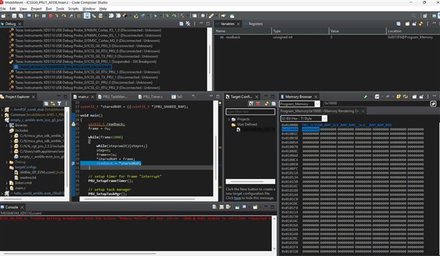
  • I am loading the referenced project as a starting point at your link, and slightly modifying the code to write to some registers (Task Manager and IEP config registers) and write to and read from Shared RAM (0x1_0000). When I write to these addresses, I do not see the values update in the memory viewer. When I try to read back any of these written values, I just get 0s. Is there something I need to do to enable access to reading or writing memory? Perhaps a missing step in the load/debug process not discussed in the Acadmy?

  • Additional details. I am trying to use the Memory Browser "fill memory" option to write a series of bytes to PRU shared RAM:

    But I get an error when trying to do so:

    This is even when I am connected and able to step through the code i have loaded.. So is there some setting in code I need to set in order to write to any of these addresses?

  • Last bit of data... I changed the code to be an array access rather than a pointer access, but tried placing the array in the shared RAM address via the DATA_SECTION pragma:

    and defining the section in the linker file:

    However when I link after compiling, I get a warning the results in failing to generate somethign I can load:

    Building target: "ICSSG0_PRU1_AFDX.out"
    Invoking: PRU Linker
    "C:/ti/ti_cgt_pru_2.3.3/bin/clpru" -v4 --define=PRU1 --define=SLICE1 --define=SOC_AM64X --define=_DEBUG_=1 -g --diag_warning=225 --diag_wrap=off --display_error_number --endian=little -z -m"ICSSG0_PRU1_AFDX.map" --disable_auto_rts --diag_suppress=10063-D --diag_wrap=off --display_error_number --warn_sections --xml_link_info="ICSSG0_PRU1_AFDX_linkInfo.xml" --entry_point=main --rom_model -o "ICSSG0_PRU1_AFDX.out" "./PRU_TaskManager.obj" "./PRU_Timer.obj" "./main.obj" "../linker.cmd"
    <Linking>
    "../main.c", line 29: warning #17003-D: relocation from function "main" to symbol "shared_mem_array" overflowed; the 17-bit relocated address 0x10000 is too large to encode in the 16-bit field (type = 'R_PRU_FOR_U16_C32_So8s16_PCM0XFFFFFFFF' (9), file = "./main.obj", offset = 0x00000068, section = ".text:main")
    warning #10015-D: output file "ICSSG0_PRU1_AFDX.out" cannot be loaded and run on a target system
     

    How to resolve?

  • Last bit of data... I changed the code to be an array access rather than a pointer access, but tried placing the array in the shared RAM address via the DATA_SECTION pragma:

    Looks like the linker creating a symbols with PRU instructions LDI 16-bit immediate values (max 0xFFFF). 

    This should work instead. Also PRU supports LDI32 for direct constants. I will also let to  to comment further.

    volatile int *shared_mem_array = (volatile int*)0x10000;
    shared_mem_array[frame] = frame + 100;

    BR

    JC

  • Hey Seth,

    Didn't have bandwidth to look into other parts of your question this weekend.

    An aside on build settings

    Just to confirm, are you developing a PRU C project in CCS?

    I am actually finally making a bunch of changes to the example.projectspec files (that is what tells CCS what settings to use for the PRU project when it imports the project). By default, all the projects were using the example.projectspec settings which would be appropriate for assembly only, but I would NOT expect them to work properly for a PRU project that includes C code.

    in-progress pull request here:
    https://github.com/TexasInstruments/open-pru/pull/125

    As of March 22 I have NOT fully tested all of these changes, I am just trying to get through all the structural changes first and then I'll start testing.

    changes so far to the example.projectspec C files can be seen here:
    https://github.com/TexasInstruments/open-pru/commits/a0226750_remove_mcuplus_dependencies/examples/empty_c/firmware/am64x-evm/icss_g0_pru0_fw/ti-pru-cgt/example.projectspec 

    Regards,

    Nick

  • Thanks I posted a bit of a cascade on Friday as I ran into several walls during my lab shift. At this point let's just say that my remaining open questions are:

    1) Are there any project/linker/etc settings I need before writing to PRU registers from PRU C code

    2) Can you point me to any explainers/docs that discuss what the PAGE 0 and PAGE 1 etc keywords are in the linker, and how they relate to the memory map in the TRM

    Per your inquiry, yes I used empty_c as my project starting point, and am developing in C (with a few mixed assembly lines for using the XIN instruction). I will take a look at your PR and see if anything sticks out. So I know what I am trying to avoid, at a high level, what sorts of settings did you notice would be potentially problematic for a C project?

  • Thanks that update work. I also managed last week to resolve the issue by defining the section in memory:

    SECTIONS

    {

       ...

       .shared_mem > PRU_SHAREDMEM, PAGE 2

    }

    And adding keyword "__far" when declaring and definig the array in the C file:

    #pragma DATA_SECTION(shared_mem_array, ".shared_mem")
    __far int shared_mem_array[100];

    DO you have a preference of one method over the other or are they both going to do the same thing under the hood?

  • Thanks that update work. I also managed last week to resolve the issue by defining the section in memory:

    SECTIONS

    {

       ...

       .shared_mem > PRU_SHAREDMEM, PAGE 2

    }

    And adding keyword "__far" when declaring and definig the array in the C file:

    #pragma DATA_SECTION(shared_mem_array, ".shared_mem")
    __far int shared_mem_array[100];

    DO you have a preference of one method over the other or are they both going to do the same thing under the hood?

  • If I am debugging code on the PRU, how do I ensure that the system level PADCONFIG settings are correctly muxed? I use CCS to connect to PRU0 directly, so there is nothing running on A53 (or other Arm core) that will set PADCONFIG or kickoff PRU processing. I am attempting to write to the PADCONFIG registers (ox000F_4000 addresses) from the PRU code itself, but I can not tell if it is working - CCS Memory Browser shows all 0s for that address range with no impact to any of my write attempts (including when unlocked kick registers for the region).