This thread has been locked.

If you have a related question, please click the "Ask a related question" button in the top right corner. The newly created question will be automatically linked to this question.

AM263X-MCAL-SDK: Query Regarding I2C1 Scan Results on AM2634 LaunchPad

Part Number: AM263X-MCAL-SDK
Other Parts Discussed in Thread: AM2634, LP-AM263, SYSCONFIG, TPIC2810

Hi Team,

I am working with the AM2634 LaunchPad kit. From the user guide and board schematics, I understand that two devices are connected on the I2C1 bus: an EEPROM device and an LED array device, with expected I2C addresses 0x52 and 0x61.

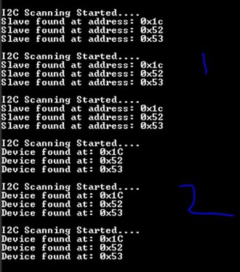
However, when I perform an I2C scan on the I2C1 bus, I am getting the following addresses:

0x1C, 0x52, and 0x53

I also noticed that the EEPROM IC connections in the board schematics appear to differ from the original IC pin configuration given in the device datasheet. I am wondering if this could be the reason for the additional detected address.

Could you please verify this once on your end by performing an I2C1 scan on the LP-AM263 hardware?

If the behavior is expected, kindly clarify the reason for the additional detected addresses.

Thanks and regards,
Sai Kiran

  • Sai,

    The addresses correspond to the following devices on the I2C1 bus:

    1. 0x1C - the default I2C address for the AM2634 device itself
    2. 0x52 - board ID EEPROM 
    3. 0x61 - LED driver

    I'm not sure why your I2C scan is reading a device with address 0x53. Are you using an SDK example or your own code?

    Regards,

    Brennan

  • Writing
    below is the code which we are using, please check it once, any mistakes is there, let us know!

    #include <stdio.h>
    #include <kernel/dpl/DebugP.h>
    #include "ti_drivers_config.h"
    #include "ti_drivers_open_close.h"
    #include "ti_board_open_close.h"

    /*
     * This is an empty project provided for all cores present in the device.
     * User can use this project to start their application by adding more SysConfig modules.
     *
     * This application does driver and board init and just prints the pass string on the console.
     * In case of the main core, the print is redirected to the UART console.
     * For all other cores, CCS prints are used.
     */
    char buf[50];
    void I2C_scan_Application(void *args)
    {

         uint8_t dummy  = 0 ;
        I2C_Transaction Trans;
        /* Open drivers to open the UART driver for console */
        Drivers_open();
        Board_driversOpen();

        I2C_Transaction_init(&Trans);
         Trans.writeBuf = &dummy;
         Trans.writeCount = 1;
         Trans.readCount = 0;
         Trans.readBuf = NULL;
    while(1)
    {

       DebugP_log("I2C Scanning Started....\r\n");
      for(int i = 7; i < 127; i++)
      {
         Trans.targetAddress = i ;
         if(I2C_transfer(gI2cHandle[0],  &Trans) == SystemP_SUCCESS)
         {
            DebugP_log("Slave found at address: 0x%02x\r\n", i);
         }
         
      }
      DebugP_log("\n");
      ClockP_sleep(1);
    }


        Board_driversClose();
        Drivers_close();
    }     
    thanks,
    S Sai Kiran
  • Hi Sai,

    Thanks for the additional information. I can provide some explanation:

    1) I2C Scan Analysis

    • 0x1C - I2C controller's own default target address
    • 0x52 - EEPROM lower 64KB bank
    • 0x53 - EEPROM upper 64KB bank

    2) Scanning detecting the controller's address

    You're correct that I2C operates in master OR slave mode at a time. During scanning, the controller operates only in master mode.
    However:

    1. The AM263x I2C peripheral has an Own Address Register (ICOAR) set to 0x1C by default
    2. When the master transmits address 0x1C on the bus, the hardware's address matching logic recognizes it
    3. This can cause an internal ACK response - a silicon-level behavior, not a protocol violation
    4. Solution: Skip scanning the own address, or change it in SysConfig to an unused value

    3) Code analysis

    There are a few issues:

    1. Using I2C_transfer() instead of I2C_probe()
      1. The SDK provides I2C_probe() specifically for device detection:
      2. int32_t I2C_probe(I2C_Handle handle, uint32_t targetAddr);
    2. Not skipping the own address (0x1C)
    3. Verify correct I2C instance - Ensure gI2cHandle[0] is I2C1

     /* Scan addresses 0x08 to 0x77 (valid 7-bit range) */
          for(uint32_t addr = 0x08; addr <= 0x77; addr++)
          {
              /* Skip controller's own address */
              if(addr == I2C_OWN_TARGET_ADDR)
              {
                  continue;
              }
    
              /* Use I2C_probe() for proper detection */
              status = I2C_probe(gI2cHandle[0], addr);
    
              if(status == SystemP_SUCCESS)
              {
                  DebugP_log("Device found at: 0x%02X", addr);
    
                  DebugP_log("\r\n");
              }
          }

    Regards,

    Brennan

  • Hi Brennan,

    Thank you for your previous input.

    This can cause an internal ACK response - a silicon-level behavior, not a protocol violation

    I understand this, but in my experience with many different master devices, including assigning slave addresses, I have never encountered a detection issue with the device's own address. Is it common in MCUs or hosts that assigning a slave address and then performing a master mode scan could cause this?

    I have updated the code as you suggested for i2c_probe, but I am still seeing the same scan results.

    • Why am I not able to detect address 0x61?

    • What is the origin of the additional address 0x53 that appears in the scan?

    I also noticed that the EEPROM IC connections in the board schematics appear to differ from the original IC pin configuration given in the device datasheet. I am wondering if this could be the reason for the additional detected address.

    did you check this, pinout seems wrong, please correct me if am wrong?

    thanks,

    Sai Kiran

  • Sai,

    1) This behavior is specific to TI's I2C peripheral implementation, not universal across all MCUs.

    The TI I2C module on AM263x has an Own Address Register (ICOAR) that is always active. Unlike some other MCU implementations where the own address is only monitored in peripheral mode, TI's silicon may ACK its own address even when operating as controller due to internal bus monitoring
    logic.

    To eliminate this false positive, change the own address in SysConfig to an address you know doesn't exist on your bus (e.g., 0x08), or simply skip 0x1C in your scan loop.

    2) LED Driver not being detected

    If you run either of the I2C LED Blink examples (Interrupt or Polling) are you able to detect the device and blink the LEDs?

    3) EEPROM detection

    0x53 is the same physical EEPROM chip as 0x52.

    The CAT23M01 is a 128KB EEPROM. Since I2C uses 16-bit internal addressing (max 64KB), the chip uses two I2C addresses to access all memory:

    Address Memory Bank
    0x52 Lower 64KB (0x00000 - 0x0FFFF)
    0x53 Upper 64KB (0x10000 - 0x1FFFF)

    This is standard for large EEPROMs - not a scan anomaly.

    Regards,

    Brennan

  • Hi Brennan,

    I tried the i2c_led_blink_interrupt_lld example project, and the LED array blinking is working correctly.

    After confirming that, I modified the i2c_led_blink_interrupt_lld.c file and replaced the LED blink logic with the I²C scan code (shared below).

    However, the scan result is still showing the same devices at addresses 0x1C, 0x52, and 0x53, and 0x61 is not being detected.

    Could you please check if there is anything wrong with the code or approach?

    Thanks,
    Sai Kiran

  • Sai,

    Can you share the code? You did not include any in the reply.

    Likely Cause: TPIC2810 Doesn't ACK Simple Probes
    The TPIC2810 LED controller uses specific command bytes: - 0x11 - Read / Write to shift register
    - 0x22 - Load output
    - 0x44 - Write immediate

    A typical I2C scan sends just an address (or address + 0x00) and checks for ACK. The TPIC2810 may not respond to this - it might only ACK
    when it receives a valid command sequence.

    Without the code, can you confirm:

    1. How does your scan probe each address?
    - Write-only probe (address + W bit)?
    - Read probe (address + R bit)?
    - Write with a data byte (what byte)?
    2. Does the scan work by checking for ACK/NACK or by timeout?

    When you can modify the code, try probing 0x61 specifically with a valid TPIC2810 read command:
    1. Send address 0x61 (write)
    2. Send command byte 0x11
    3. Restart with address 0x61 (read)
    4. Read one byte

    If that gets a response but your generic scan doesn't, then the TPIC2810 simply doesn't ACK bare address probes.

    Regards,

    Brennan

  • Hi, 

    Please Check the file Attached for code!

    I2c_Bus_scan.rar

    When you can modify the code, try probing 0x61 specifically with a valid TPIC2810 read command:
    1. Send address 0x61 (write)
    2. Send command byte 0x11
    3. Restart with address 0x61 (read)
    4. Read one byte

    might be, i will verify once.

    thanks,

    Sai Kiran

  • Sai,

    Thanks, please update me once you try using a valid TPIC2810 read command.

    Regards,

    Brennan

  • Hi Brennan,

    I have tried using I2C_Transaction instead of I2C_probe(). Currently, the TPIC2810 is responding to this.

    #include <stdio.h>
    #include <kernel/dpl/DebugP.h>
    #include <kernel/dpl/ClockP.h>
    #include "ti_drivers_config.h"
    #include "ti_drivers_open_close.h"
    #include "ti_board_open_close.h"

    /* TPIC2810 I2C details */
    #define TPIC2810_ADDR   (0x61)
    #define TPIC_CMD_READ   (0x11)

    /* Function to check TPIC2810 using proper command sequence */
    void TPIC2810_check(void)
    {
        I2C_Transaction trans;
        uint8_t txBuf[1];
        uint8_t rxBuf[1];
        int32_t status;

        /* Initialize transaction */
        I2C_Transaction_init(&trans);

        /* Command to send */
        txBuf[0] = TPIC_CMD_READ;

        trans.targetAddress = TPIC2810_ADDR;

        /* Write setup */
        trans.writeBuf = txBuf;
        trans.writeCount = 1;

        /* Read setup */
        trans.readBuf = rxBuf;
        trans.readCount = 1;

        /* Perform I2C transfer (Write + Repeated Start + Read) */
        status = I2C_transfer(gI2cHandle[0], &trans);

        if(status == SystemP_SUCCESS)
        {
            DebugP_log("TPIC2810 detected at 0x61!\r\n");
            DebugP_log("Received Data: 0x%02X\r\n", rxBuf[0]);
        }
        else
        {
            DebugP_log("No response from TPIC2810 at 0x61\r\n");
        }
    }

    /* Main Application */
    void I2C_scan_Application(void *args)
    {
        /* Open Drivers */
        Drivers_open();
        Board_driversOpen();

        DebugP_log("I2C TPIC2810 Detection Started...\r\n");

        while(1)
        {
            TPIC2810_check();

            DebugP_log("-----------------------------\r\n");

            /* Delay 1 second */
            ClockP_sleep(1);
        }

        /* Close Drivers (never reached in loop) */
        Board_driversClose();
        Drivers_close();
    }  

    I understand that some I2C devices may not acknowledge standard probe sequences, and in this case, the LED array (TPIC2810) appears to be one such device.

    Thank you for your valuable insights and guidance on this.

    Regards,
    Sai Kiran

  • Sai,

    Glad we got to the bottom of this issue! Appreciate your patience.

    Regards,

    Brennan