This thread has been locked.

If you have a related question, please click the "Ask a related question" button in the top right corner. The newly created question will be automatically linked to this question.

AM2431: AM243x CPTS module and Time Sync Router Questions

Part Number: AM2431

Hi,

We would like to add 3 features to TI SDK's source/networking/enet/core/examples/tsn/gptp_cpsw_app example for our project:
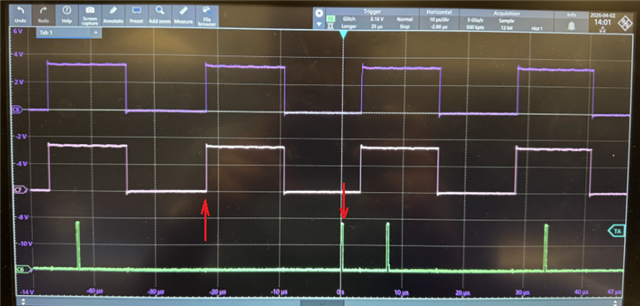
First, configure CPTS module to generate periodic GENF (CPTS_GENF0) signal (say 40kHz).

As dipicted in Technical Reference Manual, Figure 10-56. SoC Time Sync Architecture:
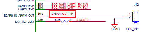
Second, configure Time Sync Router to output the CPTS_GENF0 to SYNC0_OUT, which can be routed to SYNC1_OUT_TP on AM243x EVM.

image.png
Third, connect to an interrupt handler that is triggered at the start of a CPTS_GENF0 period.

I think we know how to do generate the 40kHz CPTS_GENF0 signal. However, how to route CPTS_GENF0 to SYNC0_OUT and how to connect to interrupt handler seems to quite complex and no examples documented.

Can anyone in E2E please help with these?

We are using AM243x EVM and TI MCU plus SDK 11.01.00.17.

Thank you in advance!

  • Hi Matt,

    I observed a slight deviation in the sample code shared with you earlier to enable 40khz genF signal. The IOCTL call needs to be updated in the following way. If you are facing any linking errors, this should fix it.

    - status = Enet_ioctl(hEnet, coreId, CPSW_CPTS_IOCTL_SET_GENF, &prms);
    + ENET_IOCTL(hEnet, coreId, CPSW_CPTS_IOCTL_SET_GENF, &prms, status);


    Regarding configuring the Timesync router to send the output to physical pin, please use the following sample code.

    A clarification about the CPTS modules is, there are 2 CPTS modules in AM64x. One in CPSW IP, and one stand alone. We need to configure the CPTS which is inside the CPSW. The sample code configures the correct CPTS, which is inside the CPSW.

    /**
     * @file sample_code_TSR_init.c
     * @brief Configure GENF signal and route to SYNC0_OUT pin for AM64x
     *
     * This sample code demonstrates how to:
     * 1. Configure CPTS GENF (Generic Function) output at a specific frequency (40 KHz)
     * 2. Route the GENF signal to SYNC0_OUT pin using Timesync Router
     *
     * Timesync Router Configuration (AM64x):
     *   - Input: CPSW0_GENF0 = 21 (per cslr_intr_timesync_event_introuter0.h)
     *   - Output: SYNC0_OUT = 24 (per AM64x TRM)
     */
    
    #include <stdio.h>
    #include <stdint.h>
    #include <kernel/dpl/ClockP.h>
    #include <networking/enet/core/include/enet.h>
    #include <networking/enet/core/include/per/cpsw.h>
    #include <networking/enet/core/include/mod/cpsw_cpts.h>
    #include <drivers/hw_include/csl_types.h>
    #include <drivers/hw_include/cslr_soc.h>
    #include <drivers/hw_include/am64x_am243x/cslr_intr_timesync_event_introuter0.h>
    #include <drivers/sciclient.h>
    
    /* GENF Configuration Parameters */
    #define GENF_OUTPUT_FREQ_HZ         (40000U)     /* 40 KHz output frequency */
    #define CPTS_RFTCLK_FREQ_HZ         (200000000U) /* 200 MHz reference clock for AM64x */
    #define GENF_INDEX                  (0U)         /* Use GENF0 */
    #define GENF_POLARITY_HIGH          (1U)
    #define GENF_POLARITY_LOW           (0U)
    
    /* Timesync Router Configuration for AM64x */
    #define TIMESYNC_INTRTR0_BASE       (CSL_TIMESYNC_EVENT_INTROUTER0_CFG_BASE)
    #define TIMESYNC_IN_CPSW0_GENF0     (CSLR_TIMESYNC_EVENT_INTROUTER0_IN_CPSW0_CPTS_GENF0_0)  /* = 21 */
    #define TIMESYNC_OUT_SYNC0_PIN      (24U)        /* Output to SYNC0_OUT pin (AM64x TRM) */
    
    /**
     * @brief Configure CPTS GENF (Generic Function) output
     *
     * @param hEnet     Enet driver handle
     * @param freqHz    Desired output frequency in Hz
     * @param enable    Enable (true) or disable (false) GENF
     * @return int32_t  ENET_SOK on success
     */
    int32_t ConfigureGenF(Enet_Handle hEnet, uint32_t freqHz, bool enable)
    {
        int32_t status;
        uint32_t coreId = EnetSoc_getCoreId();
        Enet_IoctlPrms prms;
        CpswCpts_SetFxnGenInArgs genFArgs;
        uint64_t tsCompVal;
        uint32_t genFLength;
    
        /* Guard against disable path calling with freqHz=0 */
        if (freqHz == 0U)
        {
            freqHz = 1U;  /* length will be overridden to 0 in the else branch below */
        }
    
        /* Calculate GENF parameters based on desired frequency */
        /* GENF toggles every 'length' RFTCLK cycles, so length = half-period */
        /* Length = RFTCLK_FREQ / (OUTPUT_FREQ * 2) */
        genFLength = CPTS_RFTCLK_FREQ_HZ / (freqHz * 2U);
    
        /* Get current CPTS timestamp to set initial compare value */
        uint64_t currentTs = 0;
        ENET_IOCTL_SET_OUT_ARGS(&prms, &currentTs);
        ENET_IOCTL(hEnet, coreId, ENET_TIMESYNC_IOCTL_GET_CURRENT_TIMESTAMP, &prms, status);
    
        if (status != ENET_SOK)
        {
            printf("Failed to get current timestamp: %d\n", status);
            return status;
        }
    
        /* Set compare value to current timestamp + 1 second to start in future */
        tsCompVal = currentTs + 1000000000ULL; /* Add 1 second in nanoseconds */
    
        /* Configure GENF parameters */
        genFArgs.index = GENF_INDEX;
        genFArgs.length = genFLength;
        genFArgs.compare = tsCompVal;
        genFArgs.polarityInv = GENF_POLARITY_HIGH;
        genFArgs.ppmVal  = 0U;
        genFArgs.ppmDir  = CPSW_CPTS_GENF_PPM_ADJDIR_DECREASE;
        genFArgs.ppmMode = ENET_TIMESYNC_ADJMODE_DISABLE;
    
        if (enable)
        {
            printf("Configuring GENF%d:\n", GENF_INDEX);
            printf("  Output Frequency: %u Hz\n", freqHz);
            printf("  Length: %u RFTCLK cycles\n", genFLength);
            printf("  Compare Value: %llu ns\n", tsCompVal);
            printf("  Polarity: %s\n", genFArgs.polarityInv ? "High" : "Low");
    
            /* Set GENF configuration */
            ENET_IOCTL_SET_IN_ARGS(&prms, &genFArgs);
            ENET_IOCTL(hEnet, coreId, CPSW_CPTS_IOCTL_SET_GENF, &prms, status);
    
            if (status != ENET_SOK)
            {
                printf("Failed to configure GENF: %d\n", status);
                return status;
            }
    
            printf("GENF%d configured and enabled successfully\n", GENF_INDEX);
        }
        else
        {
            /* Disable GENF by setting length to 0 */
            genFArgs.length = 0;
            ENET_IOCTL_SET_IN_ARGS(&prms, &genFArgs);
            ENET_IOCTL(hEnet, coreId, CPSW_CPTS_IOCTL_SET_GENF, &prms, status);
    
            printf("GENF%d disabled\n", GENF_INDEX);
        }
    
        return status;
    }
    
    /**
     * @brief Configure Timesync Router to route GENF to SYNC0_OUT pin
     *
     * @param inputSrc   Timesync router input source
     * @param outputDest Timesync router output destination
     * @return int32_t   CSL_PASS on success
     */
    int32_t ConfigureTimesyncRouter(uint32_t inputSrc, uint32_t outputDest)
    {
        int32_t status = CSL_PASS;
        volatile uint32_t *routerReg;
    
        printf("Configuring Timesync Router:\n");
        printf("  Input Source: %u (CPSW0_GENF0 per TI SCI doc)\n", inputSrc);
        printf("  Output Dest: %u (SYNC0_OUT per AM64x TRM)\n", outputDest);
    
        /* Configure interrupt router register */
        /* Router register address = BASE + (output * 4) */
        routerReg = (volatile uint32_t *)(TIMESYNC_INTRTR0_BASE + (outputDest * 4));
    
        /* Write input source to output mapping */
        *routerReg = inputSrc;
    
        /* Verify configuration */
        if (*routerReg == inputSrc)
        {
            printf("Timesync Router configured successfully\n");
            printf("  GENF0 (input 21) -> SYNC0_OUT (output 24) routing active\n");
        }
        else
        {
            printf("ERROR: Timesync Router configuration failed\n");
            printf("  Expected: 0x%08X, Read: 0x%08X\n", inputSrc, *routerReg);
            status = CSL_EFAIL;
        }
    
        return status;
    }
    
    /**
     * @brief CPTS event notification callback (called from ISR context)
     *
     * Invoked by the CPTS interrupt handler for every event read from the FIFO.
     * For GENF, CPSW_CPTS_EVENTTYPE_TS_COMP fires on each compare match (i.e.
     * each toggle of the GENF output).
     *
     * @param cbArg     Argument passed at registration time
     * @param eventInfo CPTS event details (type, timestamp, port, etc.)
     */
    static void App_cptsEventCb(void *cbArg, CpswCpts_Event *eventInfo)
    {
        /* This callback runs in interrupt context — no blocking calls, no printf. */
        if (eventInfo->eventType == CPSW_CPTS_EVENTTYPE_TS_COMP)
        {
            /* GENF compare match: output has toggled.
             * eventInfo->tsVal holds the 64-bit CPTS timestamp of the toggle.
             * Signal a task or set a flag here; do not call printf or any
             * blocking/locking API from this context. */
        }
    }
    
    /**
     * @brief Register CPTS event callback for GENF ISR notification
     *
     * @param hEnet Enet driver handle
     * @return int32_t ENET_SOK on success
     */
    int32_t InitializeCPTS_WithGenF(Enet_Handle hEnet)
    {
        int32_t status;
        uint32_t coreId = EnetSoc_getCoreId();
        Enet_IoctlPrms prms;
        CpswCpts_RegisterStackInArgs regStackInArgs;
    
        regStackInArgs.eventNotifyCb    = App_cptsEventCb;
        regStackInArgs.eventNotifyCbArg = NULL;   /* pass app context here if needed */
    
        ENET_IOCTL_SET_IN_ARGS(&prms, &regStackInArgs);
        ENET_IOCTL(hEnet, coreId, CPSW_CPTS_IOCTL_REGISTER_STACK, &prms, status);
    
        if (status != ENET_SOK)
        {
            printf("Failed to register CPTS event callback: %d\n", status);
            return status;
        }
    
        printf("CPTS event callback registered\n");
        return ENET_SOK;
    }
    
    /**
     * @brief Main function to setup GENF and route to SYNC0_OUT
     *
     * @param hEnet Enet driver handle (from gptp_cpsw_app)
     * @return int32_t Status code
     */
    int32_t SetupGenFWithSync0Out(Enet_Handle hEnet)
    {
        int32_t status;
    
        printf("\n====== GENF to SYNC0_OUT Configuration (AM64x) ======\n\n");
    
        /* Step 1: Initialize CPTS */
        status = InitializeCPTS_WithGenF(hEnet);
        if (status != ENET_SOK)
        {
            printf("ERROR: CPTS initialization failed\n");
            return status;
        }
    
        /* Step 2: Configure GENF output frequency */
        status = ConfigureGenF(hEnet, GENF_OUTPUT_FREQ_HZ, true);
        if (status != ENET_SOK)
        {
            printf("ERROR: GENF configuration failed\n");
            return status;
        }
    
        /* Step 3: Configure Timesync Router to route GENF to SYNC0_OUT */
        status = ConfigureTimesyncRouter(TIMESYNC_IN_CPSW0_GENF0,
                                         TIMESYNC_OUT_SYNC0_PIN);
        if (status != CSL_PASS)
        {
            printf("ERROR: Timesync Router configuration failed\n");
            return ENET_EFAIL;
        }
    
        printf("\n====== Configuration Complete ======\n");
        printf("GENF0 signal (%u Hz) is now output on SYNC0_OUT pin\n",
               GENF_OUTPUT_FREQ_HZ);
        printf("Timesync Router: Input 21 (CPSW0_GENF0) -> Output 24 (SYNC0_OUT)\n\n");
    
        return ENET_SOK;
    }
    
    /**
     * @brief Update GENF frequency dynamically
     *
     * @param hEnet  Enet driver handle
     * @param newFreqHz New frequency in Hz
     * @return int32_t Status code
     */
    int32_t UpdateGenFFrequency(Enet_Handle hEnet, uint32_t newFreqHz)
    {
        printf("Updating GENF frequency to %u Hz\n", newFreqHz);
        return ConfigureGenF(hEnet, newFreqHz, true);
    }
    
    /**
     * @brief Disable GENF output
     *
     * @param hEnet Enet driver handle
     * @return int32_t Status code
     */
    int32_t DisableGenF(Enet_Handle hEnet)
    {
        printf("Disabling GENF output\n");
        return ConfigureGenF(hEnet, 0, false);
    }
    
    /* Example integration into gptp_cpsw_app main function */
    
    void gptp_app_main_function(void)
    {
        Enet_Handle hEnet;
        int32_t status;
    
        /* ... existing gptp_cpsw_app initialization code ... */
    
        /* After ENET is opened and initialized */
        status = SetupGenFWithSync0Out(hEnet);
        if (status != ENET_SOK)
        {
            printf("Failed to setup GENF with SYNC0_OUT\n");
        }
    
        /* Optional: Update frequency after some time */
        ClockP_sleep(10); /* Sleep 10 seconds */
        UpdateGenFFrequency(hEnet, 100000); /* Change to 100 kHz */
    
        /* ... rest of application ... */
    
        /* Before cleanup */
        DisableGenF(hEnet);
    }
    
    
    /*
     * Integration Notes for AM64x gptp_cpsw_app:
     * ===========================================
     *
     * 1. Add this file to your project build system
     *
     * 2. Call SetupGenFWithSync0Out() after ENET is initialized:
     *    - After Enet_open() succeeds
     *    - After CPTS is initialized
     *
     * 3. Pinmux Configuration:
     *    - Ensure SYNC0_OUT pin is configured in SysConfig
     *    - Pin should be muxed to TIMESYNC function
     *    - For AM64x: SYNC0_OUT can be mapped to available GPIO pins
     *
     * 4. Hardware Verification:
     *    - Use oscilloscope to measure signal on SYNC0_OUT pin
     *    - Expected: 40 KHz square wave (default configuration)
     *
     * 5. Frequency Calculation:
     *    - GENF toggles every 'length' RFTCLK cycles (length = half-period)
     *    - GENF Length = RFTCLK_FREQ / (Desired_Freq * 2)
     *    - For 40 KHz: 200,000,000 / (40,000 * 2) = 2500
     *    - For 100 KHz: 200,000,000 / (100,000 * 2) = 1000
     *    - For 1 MHz: 200,000,000 / (1,000,000 * 2) = 100
     *
     * 6. Timesync Router Configuration (AM64x specific):
     *    - Input 21: CPSW0_CPTS_GENF0 (CSLR_TIMESYNC_EVENT_INTROUTER0_IN_CPSW0_CPTS_GENF0_0)
     *      Note: Input 16 is CPTS0 (standalone) GENF0, NOT CPSW0
     *    - Output 24: SYNC0_OUT (per AM64x TRM)
     *    - Register offset: BASE + (24 * 4) = BASE + 0x60
     */
    

    Corresponding to the ISR, I am yet to confirm if this can work or not. But this is a viable route to trigger the event. In case it is enabled, please note that the ISR would be triggered at twice the frequency of the output signal of 40 kHz, since the toggle event will happen twice per period.

    The sync0_out signal is known to be a signal being routed outside, and is also inline with the syscfg pin outs. I will request internally to get these reviewed again.

    Please let us know if you have any queries regarding this code.

  • Hi Teja,
    Thank you for the answers. I incorporated the example code into the gptp_cpsw_app example. We saw 0V at J12 pin1 (SYNC1_OUT_TP). Also, the ISR App_cptsEventCb() is not invoked. What are we still missing?

    This is what we did:
    In C:\ti\mcu_plus_sdk_am64x_11_01_00_17\source\networking\enet\core\examples\tsn\enetapp_cpsw.c:

    static void EnetApp_enableTsSync()
    {
        ...
    -    bitSelect = CPSW_CPTS_TS_OUTPUT_BIT_17;    
    +    bitSelect = CPSW_CPTS_TS_OUTPUT_BIT_DISABLED;
        ...
    }
    
    static Pinmux_PerCfg_t gCustomPinMux[] = {
        /* ECAP0_IN_APWM_OUT (D18) - set desired mode here */
        {
            PIN_ECAP0_IN_APWM_OUT,
            ( PIN_MODE(1) | PIN_PULL_DISABLE )
        },
        {PINMUX_END, PINMUX_END}
    };
    
    void EnetApp_initAppCfg(EnetPer_AttachCoreOutArgs *attachArgs, EnetApp_HandleInfo *handleInfo)
    {
        ...
        EnetApp_enableTsSync();
    
        Pinmux_config(gCustomPinMux, PINMUX_DOMAIN_ID_MAIN);
        int32_t status = SetupGenFWithSync0Out(gEnetAppCfg.hEnet);
    }
    

    Other than the results, I have some questions regarding the same code:
    1. Can you please elaborate on how ConfigureTimesyncRouter() works?
    It looks like the sample code is writing the IR input index value to a mux control register (base: TIMESYNC_EVENT_INTROUTER0, offset: (IR output index value * 4))?
    By doing this, we route cpts_genf0 in CPSW0 to TIMESYNC_EVENT_INTROUTER0_outl_24 (PINFUNCTION_SYNC0_OUTout)?
    Is this mux control register the "TIMESYNC_INTROUTER0_INTR_MUXCNTL Register" in 10.3.2.3.1.2.1?
    But I did not seem to find the description that explains how this works in TRM.

    2. For the ISR, although we did not see any interrupts (probably due to other reasons), can you please explain why CPSW_CPTS_EVENTTYPE_TS_COMP is used?

  • Hi Matt,

    I have checked with the experts that the event callback from the same genF cannot trigger an event, thus no ISR along with it. So, we have to route it to a H/W push event, with which we can handle the interrupt. This will also help us to validate GenF creation at this stage.

    For checking internally to identify if the genF signal is correctly being generated, we can verify it by routing the signal to a H/W push event, and link a callback to it using the IOCTL "CPSW_CPTS_IOCTL_REGISTER_HWPUSH_CALLBACK". If the GenF is configured correctly, we will hit this ISR time to time. 

    On the other hand, Our hw team is looking into the details of the pin out, and we can expect the response in 1-2 days. 

    Below, I am attaching a sample code to configure SCI client to configure TimeSync router via SCI client. I was not able to validate this from my end. I will try to run this in my setup in coming 3 days.

    static void EnetApp_setTimeSyncRouter()
    {
         int32_t                             retVal;
        struct tisci_msg_rm_irq_set_req     rmIrqReq;
        struct tisci_msg_rm_irq_set_resp    rmIrqResp;
        rmIrqReq.valid_params           = 0U;
        rmIrqReq.valid_params          |= TISCI_MSG_VALUE_RM_DST_ID_VALID;
        rmIrqReq.valid_params          |= TISCI_MSG_VALUE_RM_DST_HOST_IRQ_VALID;
        rmIrqReq.global_event           = 0U;
        rmIrqReq.src_id                 = 6U;
        rmIrqReq.src_index              = 21U; // cpsw_genf0
        rmIrqReq.dst_id                 = 6U;
        rmIrqReq.dst_host_irq           = 25U; // SYNC1_OUT pin // 24 for SYNC0_OUT
        rmIrqReq.ia_id                  = 0U;
        rmIrqReq.vint                   = 0U;
        rmIrqReq.vint_status_bit_index  = 0U;
        rmIrqReq.secondary_host         = TISCI_MSG_VALUE_RM_UNUSED_SECONDARY_HOST;
    
    
        retVal = Sciclient_rmIrqSetRaw(&rmIrqReq, &rmIrqResp, SystemP_WAIT_FOREVER);
    }

    Regards,
    Teja.


  • Hi Teja,

    So it sounds like your previous approach and example code won't work.

    Thank you for your answers, but please clarify the following further:

    1. Does EnetApp_setTimeSyncRouter() replace the previous ConfigureTimesyncRouter() - to route CPSW_GENF0 to SYNC_OUT0 (now is SYNC1_OUT)?

    • If yes, please explain these:
      a. I thought you mentioned the Sciclient library does not manage this?

      b. Can you please explain why src_id and and dst_id are 6?

      c. Should dst_host_irq be an IR output index, or an interrupt source defined in mcu_plus_sdk_am64x_11_01_00_17\source\drivers\hw_include\am64x_am243x\cslr_intr_r5fss0_core0.h?
    • If not, please explain what does EnetApp_setTimeSyncRouter() do.

    2. Can you please help provide example code of how to route the CPSW_GENF0 to a cpts_hw1_push event and its ISR?


    Thank you for your help!

  • Hi Matt,

    Does EnetApp_setTimeSyncRouter() replace the previous ConfigureTimesyncRouter() - to route CPSW_GENF0 to SYNC_OUT0 (now is SYNC1_OUT)?

    Yes, it is expected to replace that. But it is only a sample code, and the correct expected dst should be sync0_out. We also got confirmation that the D18 pin refers to sync0_out from the hardware team. So, we have to configure this for #24 instead of #25.

    Can you please explain why src_id and and dst_id are 6?

    This refers to the IR Device ID mentioned in the interrupt router config in the Interrupt management descriptions for timesync router.

    Should dst_host_irq be an IR output index, or an interrupt source defined in mcu_plus_sdk_am64x_11_01_00_17\source\drivers\hw_include\am64x_am243x\cslr_intr_r5fss0_core0.h?

    It should be the IR output index for the given resource in the above documentation.

    I am planning to get a sample example working in our test setup. Since there are other activities going on in parallel, it is taking some time to carve out time for this. Please use the SCI client APIs to configure the time sync router. 

    By routing the generated signal to another hw push event, we can understand if we are correctly generating the signal, after which we can focus on getting the signal out. If the signal is not getting generated correctly, then our trials to observe the signal on the output would not be fruitful. So, please check the genF generation by using the following combination.

    1. Configure the timesync router to route the genf to one of the hw push events using sci API. (dst_host_irq from 30-37)
    2. Register the cb using the CPSW_CPTS_IOCTL_REGISTER_HWPUSH_CALLBACK IOCTL
    3. Remove the prints between setting the tsCompVal and calling the SET_GENF IOCTL

    This will confirm the genF is creating the signal correctly. Meanwhile, I will work on getting the signal routed externally

    Thanks and regards,
    Teja.

  • Thank you, Teja!

    I was able to able to see 40kHz signal on J12 pin 1, with the following changes:

    • Added Pinmux_config(gCustomPinMux, PINMUX_DOMAIN_ID_MAIN) call before enabling GENF.
    • Halved the GENF frequency calculation in ConfigureGenF():
      -  genFLength = CPTS_RFTCLK_FREQ_HZ / (freqHz * 2U);
      +  genFLength = CPTS_RFTCLK_FREQ_HZ / (freqHz);

    Also, using Sciclient_rmIrqSetRaw() and ENET_IOCTL() CPSW_CPTS_IOCTL_REGISTER_HWPUSH_CALLBACK, I was able to see the callback gets called approximate 40,000 calls in one second.
    However, I had trouble routing GENF to multiple outputs (SYNC0_OUT and CPTS_HW1_PUSH) at the same time.
    Please see my test code below:

    static int32_t EnetApp_setTimeSyncRouter()
    {
        int32_t                             retVal;
        struct tisci_msg_rm_irq_set_req     rmIrqReq;
        struct tisci_msg_rm_irq_set_resp    rmIrqResp;
    
        // CPSW_GENF0 -> SYNC0_OUT
        rmIrqReq.valid_params           = 0U;
        rmIrqReq.valid_params          |= TISCI_MSG_VALUE_RM_DST_ID_VALID;
        rmIrqReq.valid_params          |= TISCI_MSG_VALUE_RM_DST_HOST_IRQ_VALID;
        rmIrqReq.global_event           = 0U;
        rmIrqReq.src_id                 = 6U;
        rmIrqReq.src_index              = 21U; // cpsw_genf0
        rmIrqReq.dst_id                 = 6U;
        rmIrqReq.dst_host_irq           = 24U; // 24 for SYNC0_OUT
        rmIrqReq.ia_id                  = 0U;
        rmIrqReq.vint                   = 0U;
        rmIrqReq.vint_status_bit_index  = 0U;
        rmIrqReq.secondary_host         = TISCI_MSG_VALUE_RM_UNUSED_SECONDARY_HOST;
    
        retVal = Sciclient_rmIrqSetRaw(&rmIrqReq, &rmIrqResp, SystemP_WAIT_FOREVER);
        if(retVal != SystemP_SUCCESS)
        {
            return retVal;
        }
    
        // CPSW_GENF0 -> CPTS_HW1_PUSH
        rmIrqReq.valid_params           = 0U;
        rmIrqReq.valid_params          |= TISCI_MSG_VALUE_RM_DST_ID_VALID;
        rmIrqReq.valid_params          |= TISCI_MSG_VALUE_RM_DST_HOST_IRQ_VALID;
        rmIrqReq.global_event           = 0U;
        rmIrqReq.src_id                 = 6U;
        rmIrqReq.src_index              = 21U; // cpsw_genf0
        rmIrqReq.dst_id                 = 6U;
        rmIrqReq.dst_host_irq           = 30U; // 30 for CPTS_HW1_PUSH
        rmIrqReq.ia_id                  = 0U;
        rmIrqReq.vint                   = 0U;
        rmIrqReq.vint_status_bit_index  = 0U;
        rmIrqReq.secondary_host         = TISCI_MSG_VALUE_RM_UNUSED_SECONDARY_HOST;
    
        retVal = Sciclient_rmIrqSetRaw(&rmIrqReq, &rmIrqResp, SystemP_WAIT_FOREVER);
    
        return retVal;
    }

    The return value of the second Sciclient_rmIrqSetRaw() is -1 and no callback is called. If I remove the first Sciclient_rmIrqSetRaw() call, then I can see the callback gets called about 40,000 times per second, but no 40kHz output on SYNC0_OUT.

    Can you please help with following:
    1. Please check and further explain the GENF frequency calculation in ConfigureGenF().
    2. Please help with routing GENF to both SYNC0_OUT and CPTS_HW1_PUSH at the same time.

    We will test the jitters of the SYNC0_OUT between the grandmaster and slave.

    Thank you!

  • Hi Matt,

    I was able to verify that your changes with halving the genF count looks correct since I observed the same thing as well. Looks like, I had the wrong understanding of this calculation where the genF freq is not given per toggle, but rather for a full cycle. The earlier calculation was based on number of ticks needed per toggle. The current config is with number of ticks needed for full period of our target frequency signal. This has been confirmed by our experts yesterday. I was able to reproduce this from my end.

    Coming to the part where we need to route GENF to both SYNC0_OUT and HW push event, I have not tried to configure this yet, but let me check the behavior on that. If this becomes difficult, we can configure a second GENF, which will be in sync with the other GENF to trigger the second signal.

    I will keep you posted on our findings.

    Thanks and regards,
    Teja.

  • Hi Matt,

    I was able to get the interrupt along with the external signal working by using 2 GenF instances. I am attaching the same to enable this in gptp_cpsw_app example. We are looking to verify if we can use a single input GenF to create 2 outputs. We will confirm this by Monday.

    /*
     *  Copyright (c) Texas Instruments Incorporated 2023-2024
     *
     *  Redistribution and use in source and binary forms, with or without
     *  modification, are permitted provided that the following conditions
     *  are met:
     *
     *    Redistributions of source code must retain the above copyright
     *    notice, this list of conditions and the following disclaimer.
     *
     *    Redistributions in binary form must reproduce the above copyright
     *    notice, this list of conditions and the following disclaimer in the
     *    documentation and/or other materials provided with the
     *    distribution.
     *
     *    Neither the name of Texas Instruments Incorporated nor the names of
     *    its contributors may be used to endorse or promote products derived
     *    from this software without specific prior written permission.
     *
     *  THIS SOFTWARE IS PROVIDED BY THE COPYRIGHT HOLDERS AND CONTRIBUTORS
     *  "AS IS" AND ANY EXPRESS OR IMPLIED WARRANTIES, INCLUDING, BUT NOT
     *  LIMITED TO, THE IMPLIED WARRANTIES OF MERCHANTABILITY AND FITNESS FOR
     *  A PARTICULAR PURPOSE ARE DISCLAIMED. IN NO EVENT SHALL THE COPYRIGHT
     *  OWNER OR CONTRIBUTORS BE LIABLE FOR ANY DIRECT, INDIRECT, INCIDENTAL,
     *  SPECIAL, EXEMPLARY, OR CONSEQUENTIAL DAMAGES (INCLUDING, BUT NOT
     *  LIMITED TO, PROCUREMENT OF SUBSTITUTE GOODS OR SERVICES; LOSS OF USE,
     *  DATA, OR PROFITS; OR BUSINESS INTERRUPTION) HOWEVER CAUSED AND ON ANY
     *  THEORY OF LIABILITY, WHETHER IN CONTRACT, STRICT LIABILITY, OR TORT
     *  (INCLUDING NEGLIGENCE OR OTHERWISE) ARISING IN ANY WAY OUT OF THE USE
     *  OF THIS SOFTWARE, EVEN IF ADVISED OF THE POSSIBILITY OF SUCH DAMAGE.
     */
    
    /*!
     * \file  enetapp.c
     *
     * \brief This file contains the implementation of the Enet TSN example.
     */
    
    /* ========================================================================== */
    /*                              Include Files                                 */
    /* ========================================================================== */
    
    #include <stdint.h>
    #include <tsn_combase/combase.h>
    #include <tsn_combase/combase_link.h>
    #include <tsn_combase/tilld/cb_lld_ethernet.h>
    #include "nrt_flow/dataflow.h"
    #include "debug_log.h"
    #include "tsninit.h"
    #include "enetapp_cpsw.h"
    
    #define TF_USE_GENF true
    
    
    /* ========================================================================== */
    /*                              Global Variables                              */
    /* ========================================================================== */
    
    EnetApp_Cfg gEnetAppCfg =
    {
        .name = ENETAPP_DEFAULT_CFG_NAME,
    };
    
    static const uint8_t BROADCAST_MAC_ADDRESS[ENET_MAC_ADDR_LEN] = {
        0xFF, 0xFF, 0xFF, 0xFF, 0xFF, 0xFF
    };
    
    #if TF_USE_GENF
    #include <drivers/pinmux.h>
    static Pinmux_PerCfg_t gCustomPinMux[] = {
            /* ECAP0_IN_APWM_OUT (D18) - set desired mode here */
            {
                    PIN_EXT_REFCLK1,
                ( PIN_MODE(1) | PIN_PULL_DISABLE )
            },
            {PINMUX_END, PINMUX_END}
        };
    #endif
    
    
    /* these vars are shared with gptp task to configure gptp, put it in the global mem */
    static char g_netdevices[MAX_NUM_MAC_PORTS][CB_MAX_NETDEVNAME] = {0};
    /* ========================================================================== */
    /*                           Function Declarations                            */
    /* ========================================================================== */
    
    static void EnetApp_updateCfg(EnetApp_Cfg *enet_cfg)
    {
        EnetApp_getEnetInstInfo(CONFIG_ENET_CPSW0, &enet_cfg->enetType, &enet_cfg->instId);
        EnetApp_getEnetInstMacInfo(enet_cfg->enetType, enet_cfg->instId,
                                   enet_cfg->macPorts, &enet_cfg->numMacPorts);
    }
    
    #define LOG_BUFFER_SIZE (1024)
    void ConsolePrint(const char *pcString, ...)
    {
        /* Use DebugP_log() because EnetAppUtils_print() has limit bufsize */
        va_list args;
        char buffer[LOG_BUFFER_SIZE];
    
        va_start(args, pcString);
        vsnprintf(buffer, sizeof(buffer), pcString, args);
        va_end(args);
    
        DebugP_log("%s", buffer);
    }
    
    int EnetApp_initTsn(void)
    {
        lld_ethdev_t ethdevs[MAX_NUMBER_ENET_DEVS] = {0};
        int i;
        int res = 0;
        AppTsnCfg_t appCfg =
        {
            .consoleOutCb = ConsolePrint,
        };
    
        for (i = 0; i < gEnetAppCfg.numMacPorts; i++)
        {
            snprintf(&g_netdevices[i][0], CB_MAX_NETDEVNAME, "tilld%d", i);
            appCfg.netdevs[i] = &g_netdevices[i][0];
            ethdevs[i].netdev = g_netdevices[i];
            ethdevs[i].macport = gEnetAppCfg.macPorts[i];
            if (i == 0)
            {
                /* tilld0 reuses the allocated source mac, other interfaces will allocate
                 * the mac by themself */
                memcpy(ethdevs[i].srcmac, gEnetAppCfg.macAddr, ENET_MAC_ADDR_LEN);
            }
        }
        appCfg.netdevs[i] = NULL;
        if (EnetApp_initTsnByCfg(&appCfg) < 0)
        {
            EnetAppAbort("Failed to int tsn!\r\n");
        }
        if (cb_lld_init_devs_table(ethdevs, i, gEnetAppCfg.enetType,
                                   gEnetAppCfg.instId, ENET_SYSCFG_TIMESTAMP_SOURCE) < 0)
        {
            EnetAppAbort("Failed to int devs table!\r\n");
        }
        cb_socket_set_lldcfg_update_cb(EnetApp_lldCfgUpdateCb);
    
        if (EnetApp_startTsn() < 0)
        {
            EnetAppAbort("Failed to start TSN App!\r\n");
        }
        EnetAppUtils_print("%s:TSN app start done!\r\n", __func__);
    
        return res;
    }
    
    void EnetApp_printCpuLoad(void)
    {
        static uint32_t startTime_ms = 0;
        const  uint32_t currTime_ms  = ClockP_getTimeUsec()/1000;
        const  uint32_t printInterval_ms = 5000;
    
        if (startTime_ms == 0)
        {
            startTime_ms = currTime_ms;
        }
        else if ((currTime_ms - startTime_ms) > printInterval_ms)
        {
            const uint32_t cpuLoad = TaskP_loadGetTotalCpuLoad();
    
            DebugP_log(" %6d.%3ds : CPU load = %3d.%02d %%\r\n",
                      currTime_ms/1000, currTime_ms%1000,
                      cpuLoad/100, cpuLoad%100 );
    
            startTime_ms = currTime_ms;
            TaskP_loadResetAll();
        }
        return;
    }
    
    #ifdef TF_USE_GENF
    
    /* GENF Configuration Parameters */
    #define GENF_OUTPUT_FREQ_HZ         (40000U)     /* 40 KHz output frequency */
    #define CPTS_RFTCLK_FREQ_HZ         (200000000U) /* 200 MHz reference clock for AM64x */
    #define GENF_INDEX_1                (0U)         /* Use GENF0 */
    #define GENF_INDEX_2                (1U)         /* Use GENF1 */
    #define GENF_POLARITY_HIGH          (1U)
    #define GENF_POLARITY_LOW           (0U)
    
    /* Timesync Router Configuration for AM243x/AM64x
     * The TIMESYNC_EVENT_INTROUTER0 routes CPTS events to output pins/signals.
     * GENF0 (input 21) is routed to SYNC0_OUT pin for external sync output.
     * GENF1 (input 22) is routed to HW_PUSH_EVENT0 (input 30 on router output)
     * so the CPTS captures a timestamp on each GENF1 toggle — readable via
     * the CPSW_CPTS_IOCTL_REGISTER_HWPUSH_CALLBACK callback (getTsval).
     */
    #define TIMESYNC_INTRTR0_BASE       (CSL_TIMESYNC_EVENT_INTROUTER0_CFG_BASE)
    #define TIMESYNC_IN_CPSW0_GENF0     (CSLR_TIMESYNC_EVENT_INTROUTER0_IN_CPSW0_CPTS_GENF0_0)  /* router input 21: CPSW GENF0 */
    #define TIMESYNC_IN_CPSW0_GENF1     (CSLR_TIMESYNC_EVENT_INTROUTER0_IN_CPSW0_CPTS_GENF1_0)  /* router input 22: CPSW GENF1 */
    #define TIMESYNC_OUT_SYNC0_PIN      (24U)        /* router output 24: SYNC0_OUT physical pin */
    #define TIMESYNC_OUT_HW_EVENT0      (30U)        /* router output 30: CPTS HW_PUSH input 0 */
    
    
    uint32_t tsindex = 0;
    uint64_t tsVal[20] = {0};
    
    /**
     * @brief HW push event callback — invoked by CPTS driver when a HW_PUSH
     *        input is asserted (GENF1 toggle routed via Timesync Router).
     *
     * Called from interrupt context. Captures the raw 64-bit GTC counter value
     * (not CPTS nanoseconds) into a 20-entry ring buffer for later inspection.
     * GTC_getCount64() is used here because it is safe to call from ISR context;
     * ENET IOCTL calls are not safe from ISR context.
     *
     * @param cbArg      hEnet handle passed at registration (see ConfigureGenF)
     * @param hwPushNum  HW push instance number that fired (CPSW_CPTS_HWPUSH_1)
     */
    void getTsval(void *cbArg, CpswCpts_HwPush hwPushNum)
    {
        tsVal[tsindex % 20] = GTC_getCount64();
        tsindex++;
    }
    
    /**
     * @brief Configure CPTS GENF (Generic Function) output
     *
     * @param hEnet     Enet driver handle
     * @param freqHz    Desired output frequency in Hz
     * @param enable    Enable (true) or disable (false) GENF
     * @return int32_t  ENET_SOK on success
     */
    int32_t ConfigureGenF(Enet_Handle hEnet, uint32_t freqHz, bool enable)
    {
        int32_t status;
        uint32_t coreId = EnetSoc_getCoreId();
        Enet_IoctlPrms prms;
        CpswCpts_SetFxnGenInArgs genFArgs;
        uint64_t tsCompVal;
        uint32_t genFLength;
        uint64_t currentTs = 0;
        CpswCpts_RegisterHwPushCbInArgs hwPushArgs;
    
        /* Guard against disable path calling with freqHz=0 */
        if (freqHz == 0U)
        {
            freqHz = 1U;  /* length will be overridden to 0 in the else branch below */
        }
    
        /* Calculate GENF parameters based on desired frequency */
        /* GENF toggles every 'length' RFTCLK cycles, so length = half-period */
        /* Length = RFTCLK_FREQ / (OUTPUT_FREQ) */
        genFLength = CPTS_RFTCLK_FREQ_HZ / (freqHz);
    
        /* Get current CPTS timestamp to set initial compare value */
        ENET_IOCTL_SET_OUT_ARGS(&prms, &currentTs);
        ENET_IOCTL(hEnet, coreId, ENET_TIMESYNC_IOCTL_GET_CURRENT_TIMESTAMP, &prms, status);
    
        if (status != ENET_SOK)
        {
            EnetAppUtils_print("Failed to get current timestamp: %d\r\n", status);
            return status;
        }
    
        /* Set compare value to current timestamp + 1 second to start in future */
        tsCompVal = currentTs + 1000000000ULL; /* Add 1 second in nanoseconds */
    
        /* Configure GENF parameters */
        genFArgs.index = GENF_INDEX_1;
        genFArgs.length = genFLength;
        genFArgs.compare = tsCompVal;
        genFArgs.polarityInv = GENF_POLARITY_HIGH;
        genFArgs.ppmVal  = 0U;
        genFArgs.ppmDir  = CPSW_CPTS_GENF_PPM_ADJDIR_DECREASE;
        genFArgs.ppmMode = ENET_TIMESYNC_ADJMODE_DISABLE;
    
        if (enable)
        {
            EnetAppUtils_print("Configuring GENF%d:\r\n", GENF_INDEX_1);
            EnetAppUtils_print("  Output Frequency: %u Hz\r\n", freqHz);
            EnetAppUtils_print("  Length: %u RFTCLK cycles\r\n", genFLength);
            EnetAppUtils_print("  Compare Value: %llu ns\r\n", tsCompVal);
            EnetAppUtils_print("  Polarity: %s\r\n", genFArgs.polarityInv ? "High" : "Low");
    
            /* Set GENF configuration */
            ENET_IOCTL_SET_IN_ARGS(&prms, &genFArgs);
            ENET_IOCTL(hEnet, coreId, CPSW_CPTS_IOCTL_SET_GENF, &prms, status);
    
            if (status != ENET_SOK)
            {
                EnetAppUtils_print("Failed to configure GENF-%d: %d\r\n", genFArgs.index, status);
                return status;
            }
    
            EnetAppUtils_print("GENF%d configured and enabled successfully\r\n", genFArgs.index);
    
            /* Set GENF configuration */
            genFArgs.index = GENF_INDEX_2;
            ENET_IOCTL_SET_IN_ARGS(&prms, &genFArgs);
            ENET_IOCTL(hEnet, coreId, CPSW_CPTS_IOCTL_SET_GENF, &prms, status);
    
            if (status != ENET_SOK)
            {
                EnetAppUtils_print("Failed to configure GENF-%d: %d\r\n", genFArgs.index, status);
                return status;
            }
    
            EnetAppUtils_print("GENF%d configured and enabled successfully\r\n", genFArgs.index);
        }
        else
        {
            /* Disable GENF by setting length to 0 */
            genFArgs.length = 0;
            ENET_IOCTL_SET_IN_ARGS(&prms, &genFArgs);
            ENET_IOCTL(hEnet, coreId, CPSW_CPTS_IOCTL_SET_GENF, &prms, status);
    
            EnetAppUtils_print("GENF%d disabled\r\n", GENF_INDEX);
        }
    
        /* Register HW push callback for CPSW_CPTS_HWPUSH_1.
         * GENF1 is routed to HW_PUSH_EVENT0 by ConfigureTimesyncRouter, which
         * asserts the CPTS HW_PUSH_1 input on each GENF1 toggle. The CPTS driver
         * then invokes getTsval from interrupt context on every such event.
         * hEnet is passed as cbArg so the callback can issue IOCTL calls if needed
         * in a deferred (task-context) handler in the future.
         */
        hwPushArgs.hwPushNotifyCb    = getTsval;
        hwPushArgs.hwPushNotifyCbArg = (void *)hEnet;
        hwPushArgs.hwPushNum         = CPSW_CPTS_HWPUSH_1;
    
        ENET_IOCTL_SET_IN_ARGS(&prms, &hwPushArgs);
        ENET_IOCTL(hEnet, coreId, CPSW_CPTS_IOCTL_REGISTER_HWPUSH_CALLBACK, &prms, status);
    
    
        return status;
    }
    
    /**
     * @brief Configure Timesync Router to route GENF to SYNC0_OUT pin
     *
     * @param inputSrc   Timesync router input source
     * @param outputDest Timesync router output destination
     * @return int32_t   CSL_PASS on success
     */
    int32_t ConfigureTimesyncRouter(uint32_t inputSrc, uint32_t outputDest)
    {
        int32_t                             retVal;
        struct tisci_msg_rm_irq_set_req     rmIrqReq;
        struct tisci_msg_rm_irq_set_resp    rmIrqResp;
        /* Route 1: CPSW GENF0 → SYNC0_OUT physical pin
         * src_id / dst_id = 6 is TISCI_DEV_TIMESYNC_EVENT_INTROUTER0 (AM243x RM).
         * src_index 21 = GENF0 input to the Timesync Router.
         * dst_host_irq 24 = router output wired to the SYNC0_OUT pad.
         */
        rmIrqReq.valid_params           = 0U;
        rmIrqReq.valid_params          |= TISCI_MSG_VALUE_RM_DST_ID_VALID;
        rmIrqReq.valid_params          |= TISCI_MSG_VALUE_RM_DST_HOST_IRQ_VALID;
        rmIrqReq.global_event           = 0U;
        rmIrqReq.src_id                 = 6U;  /* TISCI_DEV_TIMESYNC_EVENT_INTROUTER0 */
        rmIrqReq.src_index              = CSLR_TIMESYNC_EVENT_INTROUTER0_IN_CPSW0_CPTS_GENF0_0; /* input 21: CPSW GENF0 */
        rmIrqReq.dst_id                 = 6U;  /* TISCI_DEV_TIMESYNC_EVENT_INTROUTER0 */
        rmIrqReq.dst_host_irq           = TIMESYNC_OUT_SYNC0_PIN; /* output 24: SYNC0_OUT pin */
        rmIrqReq.ia_id                  = 0U;
        rmIrqReq.vint                   = 0U;
        rmIrqReq.vint_status_bit_index  = 0U;
        rmIrqReq.secondary_host         = TISCI_MSG_VALUE_RM_UNUSED_SECONDARY_HOST;
    
        retVal = Sciclient_rmIrqSetRaw(&rmIrqReq, &rmIrqResp, SystemP_WAIT_FOREVER);
        if (retVal != ENET_SOK)
        {
           EnetAppUtils_print("TSR pin: %d routing failed: %d\r\n",
                   rmIrqReq.dst_host_irq, retVal);
        }
    
        /* Route 2: CPSW GENF1 → CPTS HW_PUSH_EVENT0
         * src_index 22 = GENF1 input to the Timesync Router.
         * dst_host_irq 30 = router output connected to the CPTS HW_PUSH_1 input,
         * which triggers the getTsval callback registered via
         * CPSW_CPTS_IOCTL_REGISTER_HWPUSH_CALLBACK.
         */
        rmIrqReq.valid_params           = 0U;
        rmIrqReq.valid_params          |= TISCI_MSG_VALUE_RM_DST_ID_VALID;
        rmIrqReq.valid_params          |= TISCI_MSG_VALUE_RM_DST_HOST_IRQ_VALID;
        rmIrqReq.global_event           = 0U;
        rmIrqReq.src_id                 = 6U;  /* TISCI_DEV_TIMESYNC_EVENT_INTROUTER0 */
        rmIrqReq.src_index              = CSLR_TIMESYNC_EVENT_INTROUTER0_IN_CPSW0_CPTS_GENF1_0; /* input 22: CPSW GENF1 */
        rmIrqReq.dst_id                 = 6U;  /* TISCI_DEV_TIMESYNC_EVENT_INTROUTER0 */
        rmIrqReq.dst_host_irq           = TIMESYNC_OUT_HW_EVENT0; /* output 30: CPTS HW_PUSH input */
        rmIrqReq.ia_id                  = 0U;
        rmIrqReq.vint                   = 0U;
        rmIrqReq.vint_status_bit_index  = 0U;
        rmIrqReq.secondary_host         = TISCI_MSG_VALUE_RM_UNUSED_SECONDARY_HOST;
    
    
        retVal = Sciclient_rmIrqSetRaw(&rmIrqReq, &rmIrqResp, SystemP_WAIT_FOREVER);
        if (retVal != ENET_SOK)
        {
           EnetAppUtils_print("TSR pin: %d routing failed: %d\r\n",
                   rmIrqReq.dst_host_irq, retVal);
        }
    
        return retVal;
    }
    
    uint32_t my_count = 0;
    void PrintMyCount()
    {
        uint32_t currTime_ms = ClockP_getTimeUsec()/1000;
    
        DebugP_log("*** INT count: %lu,  %6d.%3d sec\r\n", my_count, currTime_ms/1000, currTime_ms%1000);
    }
    
    /**
     * @brief CPTS event notification callback (called from ISR context)
     *
     * Invoked by the CPTS interrupt handler for every event read from the FIFO.
     * For GENF, CPSW_CPTS_EVENTTYPE_TS_COMP fires on each compare match (i.e.
     * each toggle of the GENF output).
     *
     * @param cbArg     Argument passed at registration time
     * @param eventInfo CPTS event details (type, timestamp, port, etc.)
     */
    static void App_cptsEventCb(void *cbArg, CpswCpts_Event *eventInfo)
    {
        /* This callback runs in interrupt context — no blocking calls, no printf. */
        if (eventInfo->eventType == CPSW_CPTS_EVENTTYPE_TS_COMP)
        {
            /* GENF compare match: output has toggled.
             * eventInfo->tsVal holds the 64-bit CPTS timestamp of the toggle.
             * Signal a task or set a flag here; do not call printf or any
             * blocking/locking API from this context. */
             
        }
        my_count++;
    }
    
    /**
     * @brief Register CPTS event callback for GENF ISR notification
     *
     * @param hEnet Enet driver handle
     * @return int32_t ENET_SOK on success
     */
    int32_t InitializeCPTS_WithGenF(Enet_Handle hEnet)
    {
        int32_t status;
        uint32_t coreId = EnetSoc_getCoreId();
        Enet_IoctlPrms prms;
        CpswCpts_RegisterStackInArgs regStackInArgs;
    
        regStackInArgs.eventNotifyCb    = App_cptsEventCb;
        regStackInArgs.eventNotifyCbArg = NULL;   /* pass app context here if needed */
    
        ENET_IOCTL_SET_IN_ARGS(&prms, &regStackInArgs);
        ENET_IOCTL(hEnet, coreId, CPSW_CPTS_IOCTL_REGISTER_STACK, &prms, status);
    
        if (status != ENET_SOK)
        {
            EnetAppUtils_print("Failed to register CPTS event callback: %d\r\n", status);
            return status;
        }
    
        EnetAppUtils_print("CPTS event callback registered\r\n");
        return ENET_SOK;
    }
    
    /**
     * @brief Main function to setup GENF and route to SYNC0_OUT
     *
     * @param hEnet Enet driver handle (from gptp_cpsw_app)
     * @return int32_t Status code
     */
    int32_t SetupGenFWithSync0Out(Enet_Handle hEnet)
    {
        int32_t status;
    
        EnetAppUtils_print("\n====== GENF to SYNC0_OUT Configuration (AM64x) ======\r\n\n");
    
        /* Step 1: Initialize CPTS */
        status = InitializeCPTS_WithGenF(hEnet);
        if (status != ENET_SOK)
        {
            EnetAppUtils_print("ERROR: CPTS initialization failed\r\n");
            return status;
        }
    
        /* Step 2: Configure GENF output frequency */
        status = ConfigureGenF(hEnet, GENF_OUTPUT_FREQ_HZ, true);
        if (status != ENET_SOK)
        {
            EnetAppUtils_print("ERROR: GENF configuration failed\r\n");
            return status;
        }
    
        /* Step 3: Configure Timesync Router to route GENF to SYNC0_OUT */
        status = ConfigureTimesyncRouter(TIMESYNC_IN_CPSW0_GENF0,
                                         TIMESYNC_OUT_SYNC0_PIN);
        if (status != CSL_PASS)
        {
            EnetAppUtils_print("ERROR: Timesync Router configuration failed\r\n");
            return ENET_EFAIL;
        }
    
        EnetAppUtils_print("\n====== Configuration Complete ======\r\n");
        EnetAppUtils_print("GENF0 signal (%u Hz) is now output on SYNC0_OUT pin\r\n",
               GENF_OUTPUT_FREQ_HZ);
        EnetAppUtils_print("Timesync Router: Input 21 (CPSW0_GENF0) -> Output 24 (SYNC0_OUT)\r\n\n");
    
        return ENET_SOK;
    }
    
    /**
     * @brief Update GENF frequency dynamically
     *
     * @param hEnet  Enet driver handle
     * @param newFreqHz New frequency in Hz
     * @return int32_t Status code
     */
    int32_t UpdateGenFFrequency(Enet_Handle hEnet, uint32_t newFreqHz)
    {
        EnetAppUtils_print("Updating GENF frequency to %u Hz\r\n", newFreqHz);
        return ConfigureGenF(hEnet, newFreqHz, true);
    }
    
    /**
     * @brief Disable GENF output
     *
     * @param hEnet Enet driver handle
     * @return int32_t Status code
     */
    int32_t DisableGenF(Enet_Handle hEnet)
    {
        EnetAppUtils_print("Disabling GENF output\r\n");
        return ConfigureGenF(hEnet, 0, false);
    }
    #endif
    
    static void EnetApp_enableTsSync()
    {
        Enet_IoctlPrms prms;
        CpswCpts_OutputBitSel bitSelect;
        int32_t status;
    #ifdef TF_USE_GENF
        bitSelect = CPSW_CPTS_TS_OUTPUT_BIT_DISABLED;
    #else    
        bitSelect = CPSW_CPTS_TS_OUTPUT_BIT_17;
    #endif
        ENET_IOCTL_SET_IN_ARGS(&prms, &bitSelect);
        ENET_IOCTL(gEnetAppCfg.hEnet, gEnetAppCfg.coreId, CPSW_CPTS_IOCTL_SELECT_TS_OUTPUT_BIT, &prms, status);
        if (status != ENET_SOK)
        {
            EnetAppUtils_print("%s: Failed to set TS SYNC OUT BIT : %d\r\n", gEnetAppCfg.name, status);
        }
        return;
    }
    
    void EnetApp_initAppCfg(EnetPer_AttachCoreOutArgs *attachArgs, EnetApp_HandleInfo *handleInfo)
    {
        /* To support gptp switch mode, we must configure from syscfg file:
         * enet_cpsw1.DisableMacPort2 = false; */
        EnetApp_updateCfg(&gEnetAppCfg);
    
        gEnetAppCfg.coreId = EnetSoc_getCoreId();
        EnetQueue_initQ(&gEnetAppCfg.txFreePktInfoQ);
        EnetAppUtils_enableClocks(gEnetAppCfg.enetType, gEnetAppCfg.instId);
        DebugP_log("start to open driver.\r\n");
        EnetApp_driverInit();
        EnetApp_driverOpen(gEnetAppCfg.enetType, gEnetAppCfg.instId);
        EnetApp_acquireHandleInfo(gEnetAppCfg.enetType, gEnetAppCfg.instId, handleInfo);
        gEnetAppCfg.hEnet = handleInfo->hEnet;
        EnetApp_coreAttach(gEnetAppCfg.enetType, gEnetAppCfg.instId, gEnetAppCfg.coreId, attachArgs);
        gEnetAppCfg.coreKey = attachArgs->coreKey;
    
        EnetApp_enableTsSync();
    #ifdef TF_USE_GENF
        Pinmux_config(gCustomPinMux, PINMUX_DOMAIN_ID_MAIN); //Enable here
        int32_t status = SetupGenFWithSync0Out(gEnetAppCfg.hEnet);
        if (status != ENET_SOK)
        {
            EnetAppUtils_print("Failed to setup GENF with SYNC0_OUT\r\n");
        }
        //UpdateGenFFrequency(hEnet, 100000); /* Change to 100 kHz */
    #endif    
    }
    
    void EnetApp_addMCastEntry(Enet_Type enetType,
                               uint32_t instId,
                               uint32_t coreId,
                               const uint8_t *testMCastAddr,
                               uint32_t portMask)
    {
        Enet_IoctlPrms prms;
        int32_t status;
        CpswAle_SetMcastEntryInArgs setMcastInArgs;
        uint32_t setMcastOutArgs;
    
        if (Enet_isCpswFamily(enetType))
        {
            Enet_Handle hEnet = Enet_getHandle(enetType, instId);
    
            EnetAppUtils_assert(hEnet != NULL);
            memset(&setMcastInArgs, 0, sizeof(setMcastInArgs));
            memcpy(&setMcastInArgs.addr.addr[0U], testMCastAddr,
                   sizeof(setMcastInArgs.addr.addr));
            setMcastInArgs.addr.vlanId  = 0;
            setMcastInArgs.info.super = false;
            setMcastInArgs.info.numIgnBits = 0;
            setMcastInArgs.info.fwdState = CPSW_ALE_FWDSTLVL_FWD;
            setMcastInArgs.info.portMask = portMask;
            ENET_IOCTL_SET_INOUT_ARGS(&prms, &setMcastInArgs, &setMcastOutArgs);
            ENET_IOCTL(hEnet, coreId, CPSW_ALE_IOCTL_ADD_MCAST, &prms, status);
            if (status != ENET_SOK)
            {
               EnetAppUtils_print("EnetTestBcastMcastLimit_AddAleEntry() failed CPSW_ALE_IOCTL_ADD_MCAST: %d\r\n",
                                   status);
            }
        }
    }
    
    void EnetApp_addBroadcastEntry(void)
    {
        EnetApp_addMCastEntry(gEnetAppCfg.enetType,
                              gEnetAppCfg.instId,
                              EnetSoc_getCoreId(),
                              BROADCAST_MAC_ADDRESS,
                              CPSW_ALE_ALL_PORTS_MASK);
    }
    
    void EnetApp_setMacAddr(uint8_t hwaddr[])
    {
        memcpy(gEnetAppCfg.macAddr, hwaddr, ENET_MAC_ADDR_LEN);
        EnetAppUtils_print("Host MAC address Set: ");
        EnetAppUtils_printMacAddr(hwaddr);
    }
    
    static void EnetApp_portLinkStatusChangeCb(Enet_MacPort macPort,
                                               bool isLinkUp, void *appArg)
    {
        EnetAppUtils_print("MAC Port %u: link %s\r\n",
                           ENET_MACPORT_ID(macPort), isLinkUp ? "up" : "down");
        cb_lld_notify_linkchange();
    }
    
    static void EnetApp_mdioLinkStatusChange(Cpsw_MdioLinkStateChangeInfo *info,
                                                 void *appArg)
    {
    }
    
    static void EnetApp_initAleConfig(CpswAle_Cfg *aleCfg)
    {
        aleCfg->modeFlags = CPSW_ALE_CFG_MODULE_EN;
        aleCfg->agingCfg.autoAgingEn = true;
        aleCfg->agingCfg.agingPeriodInMs = 1000;
    
        aleCfg->nwSecCfg.vid0ModeEn = true;
        aleCfg->vlanCfg.unknownUnregMcastFloodMask = CPSW_ALE_ALL_PORTS_MASK;
        aleCfg->vlanCfg.unknownRegMcastFloodMask = CPSW_ALE_ALL_PORTS_MASK;
        aleCfg->vlanCfg.unknownVlanMemberListMask = CPSW_ALE_ALL_PORTS_MASK;
        aleCfg->policerGlobalCfg.policingEn = true;
        aleCfg->policerGlobalCfg.yellowDropEn = false;
        /* Enables the ALE to drop the red colored packets. */
        aleCfg->policerGlobalCfg.redDropEn = true;
        /* Policing match mode */
        aleCfg->policerGlobalCfg.policerNoMatchMode = CPSW_ALE_POLICER_NOMATCH_MODE_GREEN;
    }
    
    static void EnetApp_initEnetLinkCbPrms(Cpsw_Cfg *cpswCfg)
    {
    #if (ENET_SYSCFG_ENABLE_MDIO_MANUALMODE == 1U)
        cpswCfg->mdioLinkStateChangeCb = NULL;
        cpswCfg->mdioLinkStateChangeCbArg = NULL;
    #else
        cpswCfg->mdioLinkStateChangeCb = EnetApp_mdioLinkStatusChange;
        cpswCfg->mdioLinkStateChangeCbArg = NULL;
    #endif
    
        cpswCfg->portLinkStatusChangeCb    = &EnetApp_portLinkStatusChangeCb;
        cpswCfg->portLinkStatusChangeCbArg = NULL;
    }
    
    void EnetApp_updateCpswInitCfg(Enet_Type enetType, uint32_t instId, Cpsw_Cfg *cpswCfg)
    {
        CpswHostPort_Cfg *hostPortCfg = &cpswCfg->hostPortCfg;
        /* Prepare init configuration for all peripherals */
        EnetAppUtils_print("\nInit all configs\r\n");
        EnetAppUtils_print("----------------------------------------------\r\n");
        EnetAppUtils_print("%s: init config\r\n", gEnetAppCfg.name);
    
        cpswCfg->hostPortCfg.removeCrc = true;
        cpswCfg->hostPortCfg.padShortPacket = true;
        cpswCfg->hostPortCfg.passCrcErrors = true;
        EnetApp_initEnetLinkCbPrms(cpswCfg);
        EnetApp_initAleConfig(&cpswCfg->aleCfg);
    
        /* Hardware switch priority is taken from packet's PCP or DSCP */
        hostPortCfg->rxVlanRemapEn     = true;
        hostPortCfg->rxDscpIPv4RemapEn = true;
        hostPortCfg->rxDscpIPv6RemapEn = true;
    
    #if defined (SOC_AM263PX) || defined(SOC_AM263X) || defined(SOC_AM261X)
        EnetDma_Cfg *dmaCfg;
        /* Set the enChOverrideFlag to enable the channel override feature of CPDMA */
        dmaCfg=(EnetDma_Cfg *)cpswCfg->dmaCfg;
        dmaCfg->enChOverrideFlag = true;
    #endif
    }
    
    static void EnetApp_closePort()
    {
        Enet_IoctlPrms prms;
        Enet_MacPort macPort;
        uint32_t i;
        int32_t status;
    
        for (i = 0U; i < gEnetAppCfg.numMacPorts; i++)
        {
            macPort = gEnetAppCfg.macPorts[i];
    
            EnetAppUtils_print("%s: Close port %u\r\n", gEnetAppCfg.name, ENET_MACPORT_ID(macPort));
    
            /* Close port link */
            ENET_IOCTL_SET_IN_ARGS(&prms, &macPort);
    
            EnetAppUtils_print("%s: Close port %u link\r\n", gEnetAppCfg.name, ENET_MACPORT_ID(macPort));
            ENET_IOCTL(gEnetAppCfg.hEnet, gEnetAppCfg.coreId, ENET_PER_IOCTL_CLOSE_PORT_LINK, &prms, status);
            if (status != ENET_SOK)
            {
                EnetAppUtils_print("%s: Failed to close port link: %d\r\n", gEnetAppCfg.name, status);
            }
        }
    }
    
    void EnetApp_close()
    {
        EnetAppUtils_print("\nClose Ports for all peripherals\r\n");
        EnetAppUtils_print("----------------------------------------------\r\n");
        EnetApp_closePort();
    
        /* Delete RX tasks created for all peripherals */
        EnetAppUtils_print("\nDelete RX tasks\r\n");
        EnetAppUtils_print("----------------------------------------------\r\n");
        EnetApp_destroyRxTask();
    
        /* Detach core */
        EnetAppUtils_print("\nDetach core from all peripherals\r\n");
        EnetAppUtils_print("----------------------------------------------\r\n");
        EnetApp_coreDetach(gEnetAppCfg.enetType,gEnetAppCfg.instId,
                           gEnetAppCfg.coreId,
                           gEnetAppCfg.coreKey);
    
        /* Close opened Enet drivers if any peripheral failed */
        EnetAppUtils_print("\nClose all peripherals\r\n");
        EnetAppUtils_print("----------------------------------------------\r\n");
        EnetApp_releaseHandleInfo(gEnetAppCfg.enetType, gEnetAppCfg.instId);
        gEnetAppCfg.hEnet = NULL;
    
        /* Do peripheral dependent initalization */
        EnetAppUtils_print("\nDeinit all peripheral clocks\r\n");
        EnetAppUtils_print("----------------------------------------------\r\n");
        EnetAppUtils_disableClocks(gEnetAppCfg.enetType, gEnetAppCfg.instId);
    }
    #ifdef TF_USE_GENF
    #if 0
    uint32_t my_count = 0;
    void my_handler()
    {
        my_count++;
    }
    
    void PrintMyCount()
    {
        uint32_t currTime_ms = ClockP_getTimeUsec()/1000;
    
        DebugP_log("*** INT count: %lu,  %6d.%3d sec\r\n", my_count, currTime_ms/1000, currTime_ms%1000);
    }
    
    int32_t SetCptsGenf0ToSync0_Out()
    {
        struct tisci_msg_rm_irq_set_req req = {0};
        struct tisci_msg_rm_irq_set_resp resp = {0};
        int32_t status;
    
        req.valid_params = TISCI_MSG_VALUE_RM_DST_ID_VALID |
                           TISCI_MSG_VALUE_RM_DST_HOST_IRQ_VALID;
        req.secondary_host = TISCI_MSG_VALUE_RM_UNUSED_SECONDARY_HOST;
    
        /* Hop 1: cpts_genf0 (1) -> TIMESYNC_EVENT_INTROUTER0 */
        req.src_id = TISCI_DEV_CPTS0;
        req.src_index = 1U;
        req.dst_id = TISCI_DEV_TIMESYNC_EVENT_INTROUTER0;
        req.dst_host_irq = 16U;     // cpts_genf0 ?
        status = Sciclient_rmIrqSet(&req, &resp, SystemP_WAIT_FOREVER);
        if (status != SystemP_SUCCESS)
        {
            return status;
        }
    
        /* Hop 2: TIMESYNC_EVENT_INTROUTER0 out 24 -> SYNC0_OUT */
        req.src_id = TISCI_DEV_TIMESYNC_EVENT_INTROUTER0;
        req.src_index = 1U;
        req.dst_id = TISCI_DEV_ECAP0;   // ECAP0_IN_APWM_OUT mode 1 => SYNC0_OUT ?
        req.dst_host_irq = 129U;     //CSLR_R5FSS0_CORE0_INTR_CPTS0_EVNT_PEND_0U;          // cpts_hw1_push ?
        status = Sciclient_rmIrqSet(&req, &resp, SystemP_WAIT_FOREVER);
    
    
        /* Set up ISR */
        HwiP_Params hwiPrms;
        HwiP_Object compHwiObject;
        HwiP_Params_init(&hwiPrms);
        hwiPrms.intNum   = 129U; //CSLR_R5FSS0_CORE0_INTR_CPTS0_EVNT_PEND_0U;
        hwiPrms.callback = my_handler;
        hwiPrms.args     = (void *)NULL;
        hwiPrms.isPulse     = 1;
        status = HwiP_construct(&compHwiObject, &hwiPrms);
        if(status != SystemP_SUCCESS)
        {
    		DebugP_log("*** HwiP_construct() error\r\n");
        }
    
        return status;
    }
    #endif
    
    #endif
    

    Thanks and regards,
    Teja.

  • HI Teja,

    Yes, please help on providing the solution to use a single input GENF to create 2 outputs.

    The 2 GENF instances may not work for us, since we have to worry about if these 2 GENF instances are in sync or not...

    Thank you for your help!

  • Hi Teja,
    Just wanted to update you with the jitter measurement result. We observed both grandmaster and slave generating 40kHz GENF signals. However, the two GENF signals are not phase-locked.
    It is my understanding that GENF signal is generated based on CPTS timer values. So the two GENF signals from grandmaster and slave should be locked inphase. We also observed the gptp_cpsw_app slave console shows the time difference to the grandmaster is less than 50ns.

    Question:

    How do we make the two GENF signals locked in phase? Please help.

  • Hi Matt, 

    The two genf signals will be in sync since they are driven by the same clock, and should be getting same corrections. We are still working to confirm the behaviour of timesync router to output one-to-many mapping. 

    Coming to phase locking the signals, we can do it by starting the clocks at a future time, usually current time +(offset to make it full second). But it assumes that the boards are started within 1 sec difference. 

    Currently, we are implementing similar strategy in the existing examples which use TS Out. You can refer that to that implementation for genf as well. 

    Thanks and regards,
    Teja.

  • Hey Teja, 

    I wanted to jump in, and give a bit more clarity. Matt mentioned that we are frequency locked, but I don't think that this is actually the case. On our current test setup, we are triggering on the leaders GENF output, and have a second scope probe on the follower's GENF output. We see that the Follower's GENF output is sliding across the leaders GENF output, indicating that we are potentially phase locked, but definitely not frequency locked. According to my calculations, the frequencies of the two reference clocks for GENF are only off by about 0.0714Hz, which seems like it could just be the difference in accuracty between two PLL outputs on different IC's

    I have a theory, that this is because we are using a 200 MHz PLL as the reference clock into the GENF instances on both the leader, and the follower. We are also not applying any PPM adjustments to the reference clock into the modules, as suggested by the example code. 

    Ultimately, we need a phase and frequency locked GENF output on all nodes, and I believe that there are two potential ways that we can do this. I would like some guidance from TI to figure out if either way is even a good option, and which way is preferred. 

    • Option 1 - Use the non-corrected 200MHz PLL as the Reference clock into the GENF instances, but use the CPTS PPM, Nudge, and Direction values in the GENF module to condition the clock, and keep it frequency locked
      • I think that this would work in the sense that both the CPTS module and the GENF module would run off of 200MHz clocks, so the PPM, Nudge, and direction values could be in the same ball park, but I don't think this is the preferred option, as we are applying corrections derived from the Leader and follower CPTS clocks, to the Leader and follower 200MHz PLL clocks, which may be off by different amounts. 
    • Option 2 - Use the corrected CPTS Counter as the Reference Clock to our GENF module, and leave the GENF PPM, Nudge, and Direction correction values at 0, as we have in the example code right now. 
      • I think that this is the better approach, as we are using as close to the same clock as we can GENF implementation on any given node in the TSN network. 

    Assuming that option 1 is not a good option, I would like to understand if it's even feasible to use the CPTS counter, running at 200MHz, which I believe that it already is, in order to be used as the Reference Clock for GENF. If we cannot use the CPTS counter directly, is there a conditioned clock that is conditened off of the PTP stack that we can use as the Reference Clock for GENF?

    Can you please share the feasibility of doing this, as well as how Matt can implement this into our test setup? 

    In the meantime, we will work on starting the EVM's, letting the network converge, and then starting GENF on both boards at a time in the future (current time + offset), so that we can see if the GENF signals start at the same time. This would at the very least show that we are in fact phase locked, and then we will only have to fix the issue of being frequency locked!

  • Hey Everyone, 

    Here is some more information from our testing today. We were mainly trying to verify that we maintained synchronous communication between the two CPTS modules across the Leader and Follower Boards. 

    The first thing we did, was enable the CPTS0_TS_SYNC Signal, coming out on ALV U1. We measured this signal at 3.184kHz, on J3 Pin 11 of the HSE Expansion board. When GENF0 was running, this signal did not look synced across the two boards. They started off synced, and then the follower board started drifting away. At the worst case, after running for about 2 minutes, it was off by 40us. It did not look like jitter, it looked like it was just continuously increasing it's offset to the master, until it was a full 40us away from the master. This shows me that while GENF is configured, and running, something is breaking the PTP stack, or something internal to the CPTS in a way which is making us lose our CPTS corrections

    The next thing we did, was ensure that we did not break the CPTS module in our efforts to debug and add GENF into our project. We essentially just commented out the GENF configuration, and reran the same experiment. The CPTS0_TS_SYNC Signal across both boards now looked like they were in fact correcting off of each other, and the jitter that we observed was bounded to less than 100ns. 

    Something in the implementation of GENF in our project is breaking out CPTS synchronization. If you have any suggestions on what might be causing this behavior, that would be very good. Another thing to note is that it looks like (through console outputs), that the follower board attempts to become the master board as soon as GENF configuration happens on the follower board. 

    Please help us resolve this, as it's critical that we can call GENF on any node, and have the phase and freq locked strobe that we need. 

  • Hi Calvin,

    I had setup the testbench to look for the frequency lock and phase lock issues with GenF. I was able to confirm the frequency lock issues seen by you in the context of GenF, although the exact frequency mismatch is yet to be confirmed. This is stemming from the fact that the AM64x version of enet driver is currently not applying the corrections to the genF counters. This is available in other platforms which are using Enet driver. We are currently working on confirming the test results for genF freqency and phase lock.

    Coming to the drift issue mentioned in your tests, I have not observed it in our test runs. But since we haven't specifically ran these tests, I would like to verify in our test setup to reproduce and root cause this issue. I will update this test result by end of day.

    Once we could verify that the GenF sync is stable, I will share the patch to enable it on the SDK that you are using.

    Regards,
    Teja.

  • Hi Calvin,

    I was able to test the GenF sync between 2 boards, and was able to verify the frequency and Phase lock. Here is the patch to enable the same.

    https://e2e.ti.com/cfs-file/__key/communityserver-discussions-components-files/908/0001_2D00_Add_2D00_genf_2D00_corrections_2D00_to_2D00_cpts_2D00_corrections.patch

    I was able to verify that with in the 4 hour of testing, we saw about +/-75ns difference.

    The patch also has a change to the genfArgs.compare input to make both outputs to be phase aligned, if they are started with in the difference of 1 second, and the sync signal would start output to output after a decent sync has been achieved, in this case about 20 sec. 

    This still uses 2 GenF signals, but with the way the genF corrections are applied, both genFs will stay synced.

     This shows me that while GENF is configured, and running, something is breaking the PTP stack, or something internal to the CPTS in a way which is making us lose our CPTS corrections

    I was not able to reproduce in our test setup. Can you please clarify the test setup, and verify the same on your end?

    Since the GenF signals will stay in sync, I am not currently targeting the TS sync issue seen. If you are still seeing this in your setup and have a need for this TS sync out signal (3.184 kHz) then we will look into this issue. 

    Please let us know your observations so that we can plan for next steps.

    Thanks and regards,
    Teja.

  • Hey Teja, 

    Thanks for the support. We were able to get the GENF signals phase locked, and frequency locked today, and after about 2 hours, we saw a total accumulated jitter of about 80ns. We still need help with two things: 


    1. Generate ISR Event with rising edge of GENF - I know that the TI team is working on getting this going already, just wanted to reiterate that this is still a priority. I know that there was a suggestion to instantiate a second GENF output at 40kHz, and route this out to the ISR through the TSR, however, we would like to at least verify that this GENF is the same exact output as the first GENF, and I don't think that's possible, as we would have to route that second GENF to a CPSW SYNC pin, but I don't think we have any more available. 

    2. We need to find a better way to actually start GENF. At the moment, we have two EVM's connected to each other through the CPSW ports on the board, and they are both connected to a PC running two instances of CCS, so that we can get the serial output from both EVM's. We can only program one board at a time, and furthermore, we can only have one EVM targeted at once. This means that we essentially have to have the GENF start time configured to about 2 minutes in order to even get this going. This is okay for proving that GENF is stable enough to be our strobe, however, we would love some guidance from TI if there are better ways of starting GENF for our application. We would love to wait till the TSN network has converged, and stays stable, and automatically start GENF in a way that things are phase locked. 

    Please let me know if you have any suggestions!

    Thanks, 
    Calvin Manesh

  • Hi Calvin,

    We apply the corrections to the GenF module at the same time when we apply the corrections to CPTS within few nanoseconds. So, there would be slight accuracy drop compared to CPTS, but the genF will remain in sync. Although we have only one sync_out pin available, we can configure one board to be genF_0 to sync0_out pin, and the other board to sync0_out pin, and verify the sync behavior between these two as well. These will exhibit same behavior as seen before.

    Coming to initializing the sync signal, we have to implement a layer2 based application to exchange info between boards to identify sync, and send a handshake message to communicate a common start point so that all signals will start at same point. Alternatively, we can use different boot mode to flash the final example into the OSPI flash, and power them on together. This will start all the boards connected together. For your current proof of concept, we can go with the OSPI boot mode option since it is much easier to do.

    Once you have your examples dialed in, you can flash them in OSPI and power them up together. This will make sure the examples start close to each other, and can reduce the start time from 2 mins to close to 15-20 seconds for sync to establish. You can refer to this document to use OSPI boot mode and flashing into OSPI.: https://software-dl.ti.com/mcu-plus-sdk/esd/AM243X/latest/exports/docs/api_guide_am243x/GETTING_STARTED_FLASH.html

    Thanks and regards,
    Teja.

  • Thank you, Teja.

    I have two more questions regarding this:

    1. Any update on the timesync router to output one-to-many mapping (How to route GENF0 to both sync0_out and CPTS_HW1_PUSH)?

    2. Why GENF needs to be started within 1 second between master and slave, but not TS SYNC? In the CPSW PTP example, we can start master and slave at anytime. Can you please explain what is the difference between using GENF and TS SYNC on this particular behavior?

    Thank you!

  • Hi Matt,

    1. We are reviewing the hardware behavior on our platforms, and checking from the DM side to identify the root cause. Our testing will conclude tomorrow, and will keep you posted on the results
    2. The additional time is to achieve phase lock. We can start generating the strobe signal immediately as well. But since we are validating the platform for jitter, we would want them to be phase aligned.

    Thanks and regards,
    Teja.

  • Hi Teja,

    We just did an experiment to test the latency of the ISR: Set TEST_LED2 (MCU_GPIO0_5) high at the start of the ISR, set TEST_LED2 low at the end of the ISR.

    We observed the time between the start of a GENF period, and TEST_LED2 going high is around 4 - 7 micro seconds mostly. However, occasionally this time is about 22 micro seconds. This will cause potential issues in our application.

    Here is the ISR:

    static void App_cptsEventCb(void *hwPushNotifyCbArg, CpswCpts_HwPush hwPushNum)
    {
        GPIO_pinWriteHigh(g_gpioBaseAddr, g_pinNum);
        my_count++;
        GPIO_pinWriteLow(g_gpioBaseAddr, g_pinNum);
    }


    Top row: GENF of grandmaster
    2nd row: GENF of slave
    3rd row: TEST_LED2 pulses generated in ISR (on slave)
    You can see the second pulse from the left is around 22 micro seconds after the start of the slave GENF.


    My understanding is the CPSW_CPTS_HWPUSH_1 callback is called from interrupt context. Also, there is almost nothing else in the ISR except for the GPIO toggling. Any idea of what causes this 22 micro seconds delay and how we can eliminate this delay?


    Thank you for your help!

  • Hi Matt,

    Please let me run this in our test bench and try to identify the issue. 22us delay is on the higher side than expected. I assume some critical sections are getting executed in the periodic tasks which are causing this issue. Please let me reproduce this for further analysis. Since Friday is TI india holiday, this activity will be taken up on Monday. 

    Thanks and regards,
    Teja.

  • Hi Matt,

    I was able to get the ISR behavior slightly improved with the following changes.

    1. Disabling Stats module in Enet. (This wouldn't be needed if you are not interested in the exact count of packets you are receiving)
    2. Improving the CPTS ISR Event handling to decrease the time from trigger to ISR.
    3. Moving the application from DDR to MSRAM

    Please use the below patch to enable the (1) and (2), and move the application space from DDR region to MSRAM to improve memory access issues. The range has been found to be within 1.5us to 5us most of the time, and the jitter spreading over +1.5 to +15us over a period of 30 mins. 

    Please let us know what is your tolerance range, and we can explore other possible methods to reduce the variance of ISR timing. We can also nudge the GenF clock such that we can make the ISR handling GenF to shift in Phase to better align with your tolerence goals. 

    Please let us know your test findings, and we can follow up from that.

    https://e2e.ti.com/cfs-file/__key/communityserver-discussions-components-files/908/ISR_5F00_jitter_5F00_improvement.patch

    Thanks and regards,
    Teja,.

  • Hi Teja,
    The current 4 - 7 micro-second latency is fine. The occasional 22 micro-second latency is the problem. We need to have a more consistent latency. I think your current method improves the situation, but the behavior of occasional large latency is still unchanged. It will be helpful if you can help identify what causes this 22 micro-second delay; and hopefully to have a solution to bring it down to be more consistent (say 4 - 10 microseconds). 

    Previously you mentioned this could be caused by "some critical sections are getting executed in the periodic tasks". I wonder if there are other higher priority ISRs preempting the CPSW_CPTS_HWPUSH_1 callback?

    Can you please help provide a method that gives a more consistent latency?

    Thank you for your help!

  • Hi Matt, 

    Did you also try moving the memory placement to MSRAM? Placing the freertos, enet and tsn libs in MSRAM helps in lower memory access times, this improving the jitter. We have seen similar improvements in another project as well. Meanwhile, let me check the driver for any further optimizations possible. 

    As I remember, the enet driver has implemented optimization for reducing critical sections. But let me check if any other runtime critical segments are consuming more time within the driver. This would need some analysis and probably 2-3 days time, considering that I will be away for one day. 

    Please let me know if this timeline doesn't align with your PoC timelines. We can try to find some middle ground. 

    Thanks and regards,
    Teja.

  • Hi Teja,
    Yes, please help identify what segments are causing the occasional long delay. 3 days is fine. It will take more time, but I think it is worthwhile.

    I have not tried placing the code in MSRAM. Can you please advise how to do this?

    I know this will improve the situation. But I would prefer that we understand the root cause, then address it accordingly; rather than working around it without knowing the exact cause. Also, I would prefer to keep the change of TI's SDK minimal. So I would like to keep this as our last resort.

    Thank you for your help!

  • Hi Teja,

    Just wanted to check back with you, any updates on the long delay issue? Thank you!

  • Hi Matt,

    We made some progress in bringing down the jitter down to 15us. But from your requirement, this might not be enough for your usecase. I have internally checked with other experts and ideated a new aproach to use GenF as a source clock to a timer, which will have lower SW overhead, and can be independently configured to a higher priority Interrupt, which will help in closing up the jitter spread.

    I will share the details with you by end of week. Please let me know if you would like to check the currently available changes. I can share them with you for your testing.

    Thanks and regards,
    Teja.

  • Hi Teja,

    Thank you for the update. I will wait for your complete solution at the end of the week.

    For now, can you please share more details of what you found on what is causing the occasional longer delays of the interrupts being served?

    Thank you!

  • Hi Matt,

    The major differences between your test bench and our current setup are as follows:

    1. Application is placed in MSRAM
    2. Most of the run time prints suppressed
    3. Minor optimisations in CPSW driver to handle the trigger interrupt better

    Moving the application to MSRAM improved the overall latency and the jitter from the application at OS level since MSRAM has faster access speed. In the current application, the prints over UART are interrupt based, and suppressing them had greatly reduced the spread of jitter, and made clear upper bound for the jitter, after running the example for over 15 hours. The CPSW driver optimisations brought the upper bound of the jitter slightly lower by prioritizing the trigger interrupt from the GenF slightly. The final results gave an overall spread limited to 15us from trigger.

    The new approach completely isolates the interrupt from CPSW, and uses dedicated timers which are driven by the GENF output, which can offer better interrupt handling characteristics.

    Thanks and regards,
    Teja.

  • Thank you, Teja.

    Do you mean the new approach uses GENF output as interrupt source (not cpsw_cpts_hwpush), bypassing time sync router? And this new interrupt source has a higher priority than those disrupting our current cpsw_cpts_hwpush interrupt?

    If not, please elaborate and clarify. Thank you!

  • Hi Matt,

    We are able to implement the new approach, with the interrupt priority higher than the current CPSW interrupts. With this, we are able to observe significant improvement in the jitter charecteristics, with the spread limited to under 5us, with the rest of the optimisations included as well. Once our internal testing finishes, I will share the patch to enable this in your system.

    The complete testing takes about 1-2 days. I can share the patch in a day's time.

    Thanks and regards,
    Teja.

  • Hi Teja,

    Thank you for the explanation and update. Please let me know once you have the solution ready. Thank you!

  • Hi Teja,

    Just checking back with you regarding this, what is the status of the patch now? Thank you.

  • Hi Matt,

    Here are the patches to enable the following: 

    1. Timer based ISR trigger to get better jitter performance (<5us)
    2. Phase lock between the ISR

    This patch disables the sync out signal coming to the external pin. To validate, you might need to have the sync out for that, you can remove the event based timer start the sequence, and call the timer start API at the end of timerP_init api directly. This will result in losing the phase lock, but will ensure correct jitter measurement setup.

    https://e2e.ti.com/cfs-file/__key/communityserver-discussions-components-files/908/tsn_5F00_stack_5F00_remove_5F00_print.patch

    https://e2e.ti.com/cfs-file/__key/communityserver-discussions-components-files/908/ISR_5F00_low_5F00_jitter_2800_1_2900_.patch

    Thanks and regards,
    Teja.

  • Hi Teja,
    A couple of questions regarding the patch:
    1. I assume the patch is the difference to previous patch, not to the original TI SDK. Is this correct?
    2. In Line 168 of ISR_low_jitter(1).patch (enetapp_cpsw.c), in order to get the GENF (sync out) to the external pin, we should keep the previous implementation and NOT applying the following diff, correct? If yes, will this incur eventISR() to be called every 25 micro seconds as well?

             genFArgs.index = GENF_INDEX_2;
    +#if(TIMER_ISR_TRIG_EN)
    +//        genFArgs.compare = genFArgs.compare - 1000000000ULL;
    +        genFArgs.compare = 0;
    +        genFArgs.length = (CPTS_RFTCLK_FREQ_HZ /CONFIG_TIMER0_INPUT_CLK_HZ);
    +#endif
    +

    3. In Line 412 of ISR_low_jitter(1).patch (tsnapp_cpsw_main.c), is the call of EnetApp_updatePtpMcastAddress() necessary? If yes, can you please explain?

    4. In Line 456 of ISR_low_jitter(1).patch (cpsw.c), I have different source code in Cpsw_cptsIsr() from yours:

    static void Cpsw_cptsIsr(uintptr_t arg)
    {
        Cpsw_Handle hCpsw = (Cpsw_Handle)arg;
        EnetMod_Handle hCpts = hCpsw->hCpts;
        Enet_IoctlPrms prms;
        int32_t status;
    
        ENET_IOCTL_SET_NO_ARGS(&prms);
        status = EnetMod_ioctlFromIsr(hCpts, CPSW_CPTS_IOCTL_HANDLE_INTR, &prms);
    
        /* TODO: Add ISR safe error:
         * ("Failed to handle CPTS intr: %d\r\n", status); */
        ENET_UNUSED(status);
    }

    Just to check if we are using the same version of SDK, my SDK directory name is "mcu_plus_sdk_am64x_11_01_00_17".
    In my case, do I comment out the two lines like this:

        //ENET_IOCTL_SET_NO_ARGS(&prms);
        //status = EnetMod_ioctlFromIsr(hCpts, CPSW_CPTS_IOCTL_HANDLE_INTR, &prms); 

    Please clarify. Thank you!

  • Hi Matt,

    I assume the patch is the difference to previous patch, not to the original TI SDK. Is this correct?

    Yes, this is true.

    In Line 168 of ISR_low_jitter(1).patch (enetapp_cpsw.c), in order to get the GENF (sync out) to the external pin, we should keep the previous implementation and NOT applying the following diff, correct? If yes, will this incur eventISR() to be called every 25 micro seconds as well?

    You can get the 25us interrupt with the latest changes as well. you would have to update the timer start config and other steps as mentioned before.

    In Line 412 of ISR_low_jitter(1).patch (tsnapp_cpsw_main.c), is the call of EnetApp_updatePtpMcastAddress() necessary? If yes, can you please explain?

    This is to fix another issue to handle multiple boards daisy chained. This has been found in our testing and will be fixed in future SDKs.

    In Line 456 of ISR_low_jitter(1).patch (cpsw.c), I have different source code in Cpsw_cptsIsr() from yours:

    You can ignore that diff, and leave the cptsIsr function as is. The two lines you commented are required for normal functioning of the application. Please DO NOT comment this.

    Thanks and regards,
    Teja.

  • Hi Teja,
    I had a chance to try the solution. Unfortunately, the CPSW_CPTS_HWPUSH_1 callback (in your case eventISR) was not triggered. TimerP_start() cannot be called at the exact time that GENF signal starts. Calling TimerP_start() at the end of TimerP_init() or other methods results in the ISR unable to sync to the GENF signal rising edge. Is this expected? If yes, how do we make the ISR sync with the GENF? If not, what I may have missed?

    Thank you for your help!

  • Hi Matt,

    The HWPUSH event not triggering is not expected. This is needed to align the ISR triggers on different boards. But when TimerP_start is called in the init function, it is expected to not align with GenF. Can you share your current application code so that I can verify the expected configuration?

    This has been tested on our side, and is confirmed to be working.

    Thanks and regards,
    Teja.

  • Hi Teja,

    Please see the enetapp_cpsw.c below. I believe this is equivalent to your patches.

    With this, the CPSW_CPTS_HWPUSH_1 callback is called. However, there were no external sync signals output. Also, the callback gets called constantly (every 25 microseconds?) although we only need it to be called once to trigger TimerP_start().

    If I swap the Line 432 and Line 453, which is what I had before,

    e.g.

    Line 432: rmIrqReq.dst_host_irq           = TIMESYNC_OUT_SYNC0_PIN;
    Line 453: rmIrqReq.dst_host_irq           = TIMESYNC_OUT_HW_EVENT0;

    then I have external sync signals output, but no ISR.

    Either ways cannot fulfill our requirements: Need both sync signals and ISR.

    Something is still not quite right here. Please help.

  • Hi Matt,

    With the available resources in CPSW, we can use any two of the following 3, which the application needs:

    1. TS sync Out
    2. Drive the external timer clock to generate low jitter ISRs
    3. HW Push Event to phase align the ISRs accross multiple boards

    In the case you need both TS sync and the low jitter ISRs, we would need to implement a different approach to sync the ISRs, which will need further more time and effort to formulate a sequence, if it is possible. I would like to check, is the system requirement is to have both 40 kHz strobe (sync out) and the ISRs being available at the same time? 

    Thanks and regards,
    Teja.

  • Hi Teja,
    Yes, as stated in the beginning of this thread, we would like to have these available at the same time:
    1. 40kHz sync out outputs driven by the TSN PTP counter.
    2. The ISRs associate with the start of the sync out periods.

    By the way, is it possible to raise the CPSW_CPTS_HWPUSH_1 interrupt priority to eliminate this occasional long latency? I tried to do this for CPTS interrupt at EnetOsal_registerIntr() in cpsw.c, but it did not help. I wonder if the limitation is due to HWPUSH_1 sharing the interrupt source with other CPSW interrupts (including ethernet tx, rx, ...etc.). So we ended up just raising priority of all CPSW interrupts? Also, the software overhead to handle these different types of CPSW interrupts is larger than a simple timer interrupt?

    Thank you.

  • Hi Matt,

    It is not possible to increase the HWPUSH interupt priority without increasing the remaining CPTS interrupt priorities as well. The major contributors to decrease the latency here are the parallel interrupts being triggered within the CPTS module during normal operation. Along with this, the ISR handling route for CPTS HWPUSH events are longer than the timer interrupts, which gives better performance. 

    We are internally discussing possibility of getting both phase alignment and the sync signal. I am on track to test the hardware compatibility test to check this tomorrow. If this approach works, we can enable you with the sequence, and a sample code to enable you. If the results turn negative, we would have to look for alternative methods.

    I will keep you posted on the results.

    Thanks and regards,
    Teja.

  • Hello Teja,

    I am also working with two AM243x EVMs running the TSN example from MCU+ SDK v12.00.00.26.

    I was able to test the GenF sync between 2 boards, and was able to verify the frequency and Phase lock. Here is the patch to enable the same.

    e2e.ti.com/.../0001_2D00_Add_2D00_genf_2D00_corrections_2D00_to_2D00_cpts_2D00_corrections.patch

    I reviewed this patch mentioned in the quote and integrated the relevant changes into my local SDK, specifically applying the GENF corrections in my cpsw_cpts_ioctl.c implementation. However, despite incorporating these modifications, I am still observing the same issue with phase drift.

    This makes me wonder if I might be missing an additional step or configuration that is required for proper phase synchronization.

    Test setup:

    • 2x AM243x-EVM connected via Ethernet (one gPTP master, one slave)
    • CPTS GENF0 generates a periodic signal (~8 kHz), routed via Time Sync Router (output 24) to SYNC0_OUT (pin D18)

    I also integrated the IRQ with the second GENF instance, but for now the GENF0 would be enough to get a PoC.

    Observed behavior:

    On the oscilloscope (one board used as trigger), the SYNC0_OUT signal of the other board slowly drifts over time. This indicates that the phase offset is continuously increasing and not being corrected.

    gPTP synchronization itself appears to be working correctly (small offset between master and slave). GENF signals are present on both boards, but they are not phase-locked.

    Question:

    Is there a known working example or reference implementation where two AM243x EVMs generate phase-synchronized GENF/SYNC0_OUT signals locked to gPTP like you mentioned?

    I would greatly appreciate any updated or example code demonstrating a working solution.

    Thank you!

  • Hi Silas,

    The issue you mentioned looks to be a frequency mismatch than phase lock issues. If the output of one board looks to be moving constantly in one direction beyond multiple wavelengths, then it can be confirmed to be frequency mismatch, which can be root caused to the two clocks not being in sync.

    With the above patches integrated, we are able to get both frequency lock and the phase lock. Even with only the changes applied to the library, we are able to confirm that the frequency lock is achieved. 

    Can you please make sure to clean the libraries and build them again, so that the changes made in the library takes effect? If the libraries are not rebuilt, this would not reflect the source code. Please let us know your findings.

    Thanks and regards,
    Teja.

  • Hi Matt,

    I ran the sanity checks for our approach, and we are not able to achieve the expected behaviour. Let me confirm this with our system experts and update you on the feasibility of this. 

    To get more context, is there any acceptable range for the two signals to be out of phase? 

    Thanks and regards,
    Teja.

  • Hey Teja, 


    Just wanted to maybe take a step back and define our goals once again, so that we are working towards the same goal. 


    For each TSN node, for both master and slave, we want to have two signals: a HW GENF signal, and an internal interrupt. The goal is to have a total delta between the master GENF signal, and the slave GENF signal of 50ns. This means that any offset in phase + jitter + latency should not exceed 50ns across all the nodes on the network. 


    With your help earlier, we have been able to achieve this. The issue that we would like to resolve now is the interrupt latency. Remember, we need a HW GENF signal to signal a strobe to HW devices on the network. We need a way of making sure that the software knows that this signal went out, as soon as the signal going out. This is what we are trying to do with the SW ISR. Basically, when the HW event happens, the SW needs to start loading registers for the next event. 


    Since the Interrupt will be serviced by SW, not HW, we know that there will be a bit more variation in the Latency of this ISR. This is acceptable for us, so long as the ISR latency is bounded by something reasonable, such as maybe 3 - 10 microseconds. At the moment, we are seeing the worst case ISR signal lagging the GENF signal by about 20 microseconds. With the 40kHz signal (25 microseconds), this only leaves us 5 microseconds. This much variation will not give us sufficient time to have software service the next scan, and we will essentially miss an event cycle.


    There are a few things that we would like to consider

    1. Is it possible to use the GENF external output (PIN_ECAP0_IN_APWM_OUT) as the source of the interrupt, to create a more bounded offset between the ISR and the GENF?
    2. If there's no other way, could we look into the performance of dedicating a core to run as a polling loop to just sit there and watch the GENF signal, and create the highest priority interupt on that core, to ensure that we don't compete with any other processes?

    Thanks, 

    Calavin Manesh

  • Hi Teja,

    thanks again for your input — I took a deeper look at the mechanism behind synchronization in TSN / 802.1AS and how it applies to our use case.

    From my current understanding, the behavior we see is expected: 802.1AS provides a common, highly accurate time base across all devices, but it does not distribute a “start interrupt” over the network. Instead, each node generates its own trigger locally once its synchronized clock reaches a defined point in time.

    This explains the issue we are currently facing:

    • If devices start nearly at the same time, they are naturally aligned.
    • If a device starts later or rejoins the network, it synchronizes its clock correctly, but not its cycle phase, which leads to the observed offset.

    To solve this properly, it seems we need an additional mechanism on top of gPTP, as you mentioned before... for example a handshake or a defined alignment strategy.

    In this context, I wanted to ask:
    Do you think GENF is the right mechanism to achieve this kind of deterministic and phase-aligned startup, or would it be possible to generate a 125 µs sync signal using TS_SYNC?

    From my current understanding, what we really need is a mechanism that ensures every node,(regardless of startup or reconnection) timelocks onto the same cycle phase derived from the global gPTP time.

    Our goal is to guarantee that devices:

    • always synchronize to the same cycle,
    • recover cleanly after reconnect,
    • and never introduce a phase offset into the system.

    I’d be very interested to hear your thoughts on whether GENF is the right building block to achieve this goal.

    Best regards,
    Silas

  • Hi Calvin,

    If you are open to generating the ISR with the external GPIO trigger driven by the strobe signal itself, I think we can do it. Let me check with our team and get back to you with an update.

    I don't think we need to have a dedicated R5 to handle the ISRs. We should be able to handle it within a single core. Once we have a setup running at our end, I will share the code, and results with you on this.

    Thanks and regards,
    Teja.

  • Hi Silas,

    We can work with the available APIs to handle your usecase, while maintaining a clean recovery feature. We would need to pass down a trigger from cpsw_handlelinkup to application context to reconfigure the GenF signals. With this mechanism, instead of setting the GenF start time based on the time start each board, we can start it based on the link up which will give more chance of getting the Phase alignment correct. But this means, we would have a longer time to recover from link down to generating the GenF.

    For your usecase, GenF is still the way to go, since theTS_SYNC maxes out in frequency at 3.745 kHz. So, we wouldn't be able to achieve a 125 µs signal from TS_SYNC.

    Let us know if you have any further queries.

    Thanks and regards,
    Teja.

  • Hi Teja,

    Yes, as I explained before, although the current solution gives pretty low latency most of the time, the problem is this non-deterministic behavior of worst case 20 microseconds latency. This gives us only 5 microseconds (20% of a strobe period) of time to process data.

    It will work for our application if the strobe signal driven ISR gives a slightly higher but deterministic latency (say worst case 7 - 10 microseconds). This guarantees we have at least 15 microseconds to do our processing.

    Thank you.