

Part Number: AM2612
Other Parts Discussed in Thread: UNIFLASH
Hi Team,
Customer is programming AM2612 on their own board, but it not works through Uniflash, could you please help to check the log and point out next step? Thanks.

Hi,
Once you have a custom board ready, please make sure you can follow the steps below properly:
Please note that the steps below are to be followed assuming that your hardware schematics is correct(Make sure you have verified the schematics by TI experts):
1. Put the board in dev boot mode. If you have the boot switches present on your custom board, if not, then move to step 2.
2. Try to load the Hello World program using the method explained here: Link
3. If the Hello World is running successfully, then move to step 2.
1. Switch the boot mode pins to flash boot mode, i.e., OSPI/QSPI/xSPI. More details here, Or If your custom board has boot switches fixed, then proceed ahead
2. Open CCS and follow the steps here: Link. Once this is done, you will see GEL Output on the CIO console in CCS, verify that boot mode is a recognized boot mode like below:(Highlighted green colour)

3. If it is not a valid boot mode, go back to schematic design and get the SOP pin connection fixed.
4. If it is correct, then go to Step 3.
1. If you have come to step 3, it means your SOP hardware schematics are correct. Now, we need to validate the Flash connection on the board.
2. Go to CCS, Import the project from SDK: AM261x MCU+ SDK: OSPI Flash IO
3. Edit the syscfg and follow this guide to add custom flash support: AM261x MCU+ SDK: Adding Support For a Custom Flash Device.
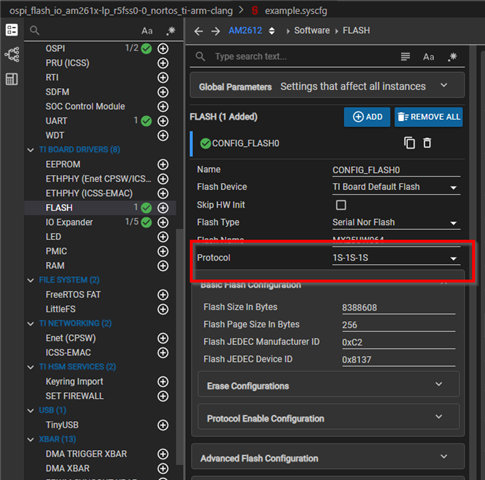
Make sure to disable the PHY mode and DMA mode when testing the OSPI flash IO example/ or during the first few test runs. These are needed if you run Flash at a higher speed, which is not recommended when you are starting to add the new Flash support. Also, it's always recommended to start from 1s-1s-1s protocol, then move up to 1s-1s-4s, and then to 1s-1s-8s, then 8s-8s-8s(*s should be used only when you are using OSPI flash). If you are using QSPI flash, then go up to 4s only.

Depending on the flash you are using, you need to adjust the flash offset in the ospi_flash_io.c file in the CCS project:
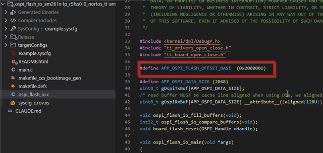
You do not need to follow point 3 if you are using the same flash as the launchpad(AM261x-LP Rev A).
4. Once the above point (3) is complete, try to run the program following the same method as Link (instead of hello world, load the ospi_flash_io binary)
5. If the test is successful, then change the protocol to the value you have fixed on the custom board or protocol of your choice. If the test passes, then we are good to go to Step 4
If any of the above steps fail, if could point to two things: a Flash HW schematics issue or an error in creating a custom flash config. If 1s-1s-1s mode fails, it is more likely a flash HW issue. At this point, please raise an e2e request attaching your syscfg, FullHW schematics, and OSPI IO project.
1. Until we were running code from RAM(not from flash), we will now move to the crucial step of booting the custom board from flash.
2. First, using the same flash configuration as in Step 3 (successful run only), build flasher_jtag_binary located at .mcu_plus_sdk\tools\flasher\jtag_uniflash\am261x-lp\r5fss0-0_nortos. in the MCU Plus SDK, import the flasher_jtag project in CCS, modify the syscfg, and build the project, save the binary. More details: Link
This binary will be used with the Uniflash tool. Follow the steps here to integrate a custom flasher binary: Follow this Link on using a custom flasher in Uniflash.
3. Go to Step 5 for building a custom SBL for your custom board
1. TI SDK provides a lot of SBL examples for users to get started with. If your goal is to boot from flash, then you need to use SBL OSPI MCELF
2. Import the SL OSPI MCELF project in the CCS, Open syscfg, and edit the flash configuration as explained in Step 3 or AM261x MCU+ SDK: Adding Support For a Custom Flash Device. ,
3. You may need to modify other components like IOMUX, LED, etc., depending on how they are present on the board.
4. Next rebuild the sbl and save the sbl_ospi_mcelf.tiimage in directory same as jtag_flasher.out(step4)
5. Open the Uniflash tool and select the XDS110 pop-up as it appears, then in the flashing screen, select the custom SBL you have built, and then select the custom flasher as described here: Link
Flash it; if past steps are successful, then this step should also succeed. If there are issues, then go back and revisit the steps, or you can create an e2e thread with the details on each step with logs, which will help us debug faster.
1. Since SBL OSPI MCELF requires you to flash the application every time, if you want to debug the application directly via CCS, you should use SBL NULL as described here:
SBL NULL allows you to boot the SBL from Flash, then initializes the SOC, and allows the user to load the .out application program via JTAG using any IDE like CCS, IAR, or even a command line-based debugger like OpenOCD.
**4s mode or QSPI mode requires enabling the QE bit, which is mostly non voltile in most flash, manufacturer does not set it, you will need to set it, if you want to use QSPI mode, this can be set using OSPI flash io example, by setting the QE configuration in the syscfg, refer to QE bit in flash datasheet for the QE mode:

