This thread has been locked.

If you have a related question, please click the "Ask a related question" button in the top right corner. The newly created question will be automatically linked to this question.

AM263P4-Q1: AM263px-cc reading ADC result with variable potentiometer

Part Number: AM263P4-Q1
Other Parts Discussed in Thread: TMDSHSECDOCK-AM263, TMDSHSECDOCK, SYSCONFIG

Hi TI team,

We were debugging the ADC channel AM263p control card (PROC159B(001)) with the potentiometer in the docking station(TMDSHSECDOCK-AM263). But we're not getting the desired result in the ADC counts, If I vary from 0V to 2.2V value getting 4095 value.image.png I've attached the result below:
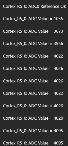


Suggest a way to get the result.

Thanks & regards,
Aravind R


  • Hi,

    I apologize as the expert is currently OoO. Please expect a reply when they return at the end of the week or the beginning of next week.

    Kind regards,
    AJ Favela 

  • Hi,

    Thanks for the update. I’ll await their response. In the meantime, please let me know if there’s anything else I can provide to help move things forward.

    Thanks & regards,
    Aravind R

  • Hi,

    Please verify the AM263Px control card ADC reference switch settings first. The AM263Px ADC examples use the 1.8-V reference path, and the docking-station potentiometer is derived from 3.3 V. If the ADC input exceeds the ADC reference, the conversion result will saturate at 4095. Also confirm the docking-station jumper settings:

    Best Regards,

    Masoud

  • Hi Masoud,


    Thanks for the response.

    Also confirm the docking-station jumper settings

    We tried using both ADC channels with op-amps connected to potentiometers and varied the input from 0, but the results were not as expected. Even at high impedance, it is reading 4095, as well as with 1.8V and 3.3V inputs.

    Instead of TMDSHSECDOCK-AM263, we tried using TMDSHSECDOCK and connected an external input. It is working fine except for the ADC0_AIN0 pin.

    Could you please suggest how to get the correct output for the signal we are feeding into ADC0_AIN0?

    Thanks & regards,
    Aravind R

  • Hi Aravind,

    My previous comment is still exist. Please first verify the ADC reference switch settings on the AM263Px control card.

    The AM263Px MCU+ SDK ADC examples are intended to run with the 1.8-V reference path, and the docking-station potentiometer is derived from 3.3 V. If the ADC input goes above the selected ADC reference voltage, the conversion result will saturate at 4095, which matches the behavior you are seeing.


    For ADC0_AIN0:

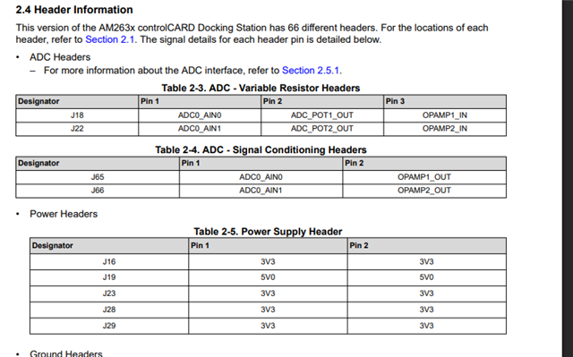
    J18 pins 1-2 = potentiometer directly to ADC input

    J18 pins 2-3 + J65 pins 1-2 = potentiometer through op-amp path

    Best Regards,

    Masoud

  • Hi Masoud,

    Sorry for not mentioning the details in the previous reply, we verified with Switch and then the J18 & J65 too, the point is just for quick testing, connected the ADC0_AIN0 to GND, still it is reading the 4095 in the output. Please clarify this

    Thanks & regards,
    Aravind R

  • Hi Aravind,

    Please let me recreate the issue on my side with CC and I'll get back to you soon.

    Best Regards,

    Masoud

  • Hi Aravind,

    There is one more thing we need to take care for ADC0_AIN0. This channel has been muxed with DAC output:

    You'll have to push the "SEL" pin to HIGH to access ADC0_IN0:

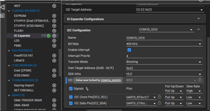
    You can use SysConfig to automatically generate the initialization for I2C and IO expander TCA6424ARGJR.

    Best Regards,

    Masoud

  • Hi Masoud,

    Thanks for your response. As per the below image, I2C configuration only I2C0 needs to be selected, but the I2C Instance is I2C2 (Value was locked by CONFIG_IOEXP0) is present. So needs to change here anything in the configuration or it will work as it is??

    Thanks & regards,
    Aravind R 

  • Yes, I2C2 is correct one.

    Best Regards,

    Masoud