This thread has been locked.

If you have a related question, please click the "Ask a related question" button in the top right corner. The newly created question will be automatically linked to this question.

MSPM0L1306: Comparator current is too high

Part Number: MSPM0L1306

Hello,

I use the comparator to wakeup the  MSPM0L1306 from standby mode 1. It works but the power consumption during the sleep is higher than expected.

I tried to disable the comparator before going to standby 1 : the comparator consume approximately 22 uA when it is enabled during the sleep mode.

The component datasheet indicates that the comparator current is 0.8 uA typical (ULP mode with DAC).

static DL_COMP_Config COMP_0Config_STR = {
    .channelEnable = DL_COMP_ENABLE_CHANNEL_POS,
    .mode          = DL_COMP_MODE_ULP,
    .negChannel    = DL_COMP_IMSEL_CHANNEL_0,
    .posChannel    = DL_COMP_IPSEL_CHANNEL_0,
    .hysteresis    = DL_COMP_HYSTERESIS_NONE,
    .polarity      = DL_COMP_POLARITY_NON_INV
};
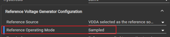
static const DL_COMP_RefVoltageConfig cCOMP_0VRefConfig_STR = {
    .mode           = DL_COMP_REF_MODE_STATIC,
    .source         = DL_COMP_REF_SOURCE_VDDA_DAC,
    .terminalSelect = DL_COMP_REF_TERMINAL_SELECT_NEG,
    .controlSelect  = DL_COMP_DAC_CONTROL_SW,
    .inputSelect    = DL_COMP_DAC_INPUT_DACCODE0
};

Do you have any idea of the cause of this current leakage ?

The comparator output doesn't change during the current measure. Input is low, without noisy signal. 
I use the positive input on IO26, negative input is the voltage from DAC, output pin is not enabled.

Regards

  • Hi,

    I have tested from my side with code in LP. It should be no problem.

    Could you try below code, and change to the related pins for IN+ compatible with your board.

    Let's see if the high current is caused by you board or your own code.

    comp_lowPower.zip

    Regards,

    Zoey

  • @Zoey Wei
    Hi,
    Thank you for your fast answer.
    I imported your project but I need to configure more IO to have it running correctly on my custom board.

    Anyway, I tried to compare the configurations and I did some quick tests on my actual firmware.
    I see a difference on the DAC voltage setting, please see my measurements below : 

    DACCODE 0 value  Average current on the board (µA)  Current consumed by the comparator driver (µA)
     0x00 (with comp disabled before sleep) 55  +0
    0x00 61.6 + 6.6
    0x02 64 + 9
    0x05 66 + 11
    0x10 66 + 11
    0x30 73.4 + 18.4
    0x60 76.9 + 21.9
    0x80 77.8 + 22.8
    0xA0 76.8 + 21.8
    0xD0 73

    +18

    0xFF 56

    + 1

    It seems the DAC output value influences directly the power consumption.
    Comp + DAC activation (with 0v out)  = +6.6 uA
    Comp + DAC at 1.65Vdc = +22uA (probably the biggest over consumption with this setting).

    I observed that current is growing with DACCODE value up to middle range (1.65Vdc for 3.3V supply) then decrease up to 1uA over consumption.

  • Hi,

    Thanks for your information.

    I have tested from my sides with different DAC setting, and the result is keep constant and within specs.

    Not sure if it possible that you can share your COMP part project that can reproduce the issue with me? Or maybe you can use the project I shared previously in the LP-MSPM0L1306 and check if the current has increased.

    My setting:

    LaunchPad: remove the almost all jumpers

    MCU enter into STOP mode (disable the COMP, the basic MCU current consumption = 382uA)

    DAC setting: DACCODE = 0x80, as the IN- = 1.66V


  • Hello,

    I'm coming back to this topic.
    I changed the Reference operating mode to "Sampled" and then the current have been reduced.

    I experienced an issue that I want to desbribe here because I think it's not a normal behavior. I found a workaround which is described below.

    I am now using the comparator in ULP mode, with DAC on sampled operating mode (only the dac, not the comparator itself). 
    I have an external signal to the PA26 pin routed to the comparator positive input. 
    I tried to wakeup the MCU from standby1 with the comparator output change.

    Sometimes it works, but most of the time it doesn't work at all. Sometimes it works but with a big delay and I missed some information on my signal.

    I tried a lot of configurations (even with async fast wakeup request) but the problem is still there. With STOP2 mode I have no issue at all.

    I think the comparator missed some interrupts on standby 1 mode.

    This is the workaround I used.

    • Set PA26 as input no pull, with interrupt on rising edge.
    • Do not configure the positive input of the comparator on pin PA26 (generates comparator with positive input disabled). This is to avoid errors in CC configuration tool.
    • Set low power mode to standby1.
    • Handler for GPIO 26 interrupt is void, but interrupt is active.
    • Handler for comparator interrupt call my process code.

    This way, there is no interrupt missed. Probably because the GPIO interrupt wakes up the MCU and the comparator output changed flag is already set (I only use the comparator interrupt handler for my data treatment).

  • Hi Alexandre,

    Thanks for pointing out!

    May I know which the input signal frequency? And duty cycle? I am just wondering, if the period of input signal is long enough for MCU to wake up from standby1 mode.

    Regards,

    Zoey

  • Hi Zoey,
    The input signal is an UART at 4800 bauds over an optical interface. 
    The bit duration is 208µs, and due to the hardware constraints (signal rise time / fall time) I think the minimum "high" time period (over the comparator threshold) is approximately 160us.
    I need to wake-up on the first start bit which is a low to high edge.
    On the MCU wakeup, I use a periodic interrupt on the timer to get the signal level with "DL_COMP_getComparatorOutput" for the 8 data bits. 
    The MCU doesn't sleep until the end of the frame (timeout detection when no more data received).