This thread has been locked.

If you have a related question, please click the "Ask a related question" button in the top right corner. The newly created question will be automatically linked to this question.

MSPM33C321A: MSPM33C321A: HSADC Unable To Reach Max Frequency

Part Number: MSPM33C321A
Other Parts Discussed in Thread: SYSCONFIG

I am using the LP-MSPM33C321A and I have used the example project hsadc_max_freq_dma as a starting point for my development and have configured my the clocks exactly the same as the example project does which uses errata workaround #1 for the SYSPLL that may lock on to the wrong frequency. I am using the DMA0 and timerA with the exact same configuration that CCS uses in the example except that I am using transfer mode: DL_DMA_FULL_CH_REPEAT_SINGLE_TRANSFER_MODE

To give more context, I have set MCLK to 160MHz and use PA27 to take in 1us pulses from a signal generator at 10kHz. However, I am only able to sample at ~2.5MSPS instead of the advertised 9.43MSPS and I know this by toggling pin PA22 with an ISR. I am using the ping pong buffer feature, so I am using early interrupts when one half of a buffer is full and an interrupt when the buffer finishes. My ADC sample count is 2048 samples/half and my frequency from PA22 is 1.22 kHz(or 1,22y halves/second) which leaves me at ~2.51MSPS. If MCLK is set 160MHz and I use TIMERA0_0 to trigger SOC with a TIMER_LOAD_VALUE of 16, should I not be seeing 9.54MSPS from my calculations? It is as if my results are being divided by 4.

  • Hi Eric,

    Could you give me more details on how the ping pong buffer is configured? My concern is if there's some delay in the ADC IRQ this could be causing some throttle and limitation on your performance.

  • I am using one DMA channel per ADC configured in DL_DMA_FULL_CH_REPEAT_SINGLE_TRANSFER_MOD.
    My destination buffer is uint16_t[2][2048], two 2048-sample halves laid out, 4096 half-words total per ADC.
    My source is the ADC result register (ADCRESULT0), SrcIncrement = ADDR_UNCHANGED, half word width.
    Destination is start of the [2][2048] buffer, destIncrement = ADDR_INCREMENT, half word width.
    Transfer size: 2 x 2048 = 4096 half words per cycle.

    I use  DL_DMA_Full_Ch_setEarlyInterruptThreshold(DMA0, 0, DL_DMA_EARLY_INTERRUPT_THRESHOLD_HALF);

    so the DMA fires with early IRQ when 2048 transfers have completed (i flag whe half[0] is full).

    Then I have a done/full IRQ when 4096 rransfers have completed (half[1] full).

    TIMA0_0 publishes a zero event on channel 1 at 9.4MHz, both ADCs subscribe and trigger SOC0. SOC0 completion fires DMA_INT_1.

    // helper function to help bring up both configs
    // for the ADC0/ADC1 at once with DMA
    static void init_hsadc(adc_module_e mod)
    {
    hsadc_ADC_LITE_REGS_Regs *adc = modules[mod].ctrl;

    DL_HSADC_setClockDivideRatio(adc, DL_HSADC_CLOCK_DIVIDE_1_0);
    DL_HSADC_SOCChannelSelect(adc, DL_HSADC_SOC_NUMBER0, DL_HSADC_ADCIN_0);
    DL_HSADC_setupSequencer(adc, DL_HSADC_SEQ_NUMBER1, 16, DL_HSADC_TRIGGER_GEN_SUB_0,
    DL_HSADC_SOC_NUMBER0);
    DL_HSADC_enableSequencer(adc, DL_HSADC_SEQ_NUMBER1);
    DL_HSADC_setSampleCapReset(adc, DL_HSADC_SEQ_NUMBER1, DL_HSADC_SAMPCAPRESET_HALF_VREFHI);
    DL_HSADC_setEndOfSequencer(adc, DL_HSADC_SOC_NUMBER0);

    // DMA trigger wiring on ADC side
    DL_HSADC_DMAInterruptStatusClear(adc, DL_HSADC_DMA_INT_1);
    DL_HSADC_enableDMAContinueToInterruptMode(adc, DL_HSADC_DMA_INT_1);
    DL_HSADC_DMAInterruptSourceSelect(adc, DL_HSADC_DMA_INT_1, DL_HSADC_SOC_NUMBER0);
    DL_HSADC_enableDMAInterrupt(adc, DL_HSADC_DMA_INT_1);

    // Subscribe to event fabric channel 1 (timer publishes here)
    DL_HSADC_setSubscriberChanID(adc, DL_HSADC_SUBSCRIBER_INDEX_0, 1);

    DL_HSADC_PowerUp(adc);


  • is FULL_CH_REPEAT_SINGLE_TRANSFER_MODE expected to keep up with 9.375 MSPS, or does the per-sample arbitration overhead of full-channel mode prevent that? And if so, what's the recommended pattern for continous (ping-pong) streaming at max rate on this part?

  • Hi Eric,


    Sorry for the delays. I did a similar test with the SDK example an ran into a similar issue getting around 5Mhz of performance. I'll update you once I have a more firm answer on the root cause and how to reconfigure it.

  • No worries, thanks for the response. Just to clarify, my use case is continuous streaming as opposed to the SDK example's one shot burst of 2000 samples DMA block (DL_DMA_FULL_CH_REPEAT_SINGLE_TRANSFER_MODE). 

    So my target architecture is:

    - ADC0+ADC1 triggered simultaneously from the same TIMA_0 zero event  

    - One DMA channel per ADC, in DL_DMA_FULL_CH_REPEAT_SINGLE_TRANSFER_MODE

    - ping pong via early IRQ at half threshold and continuous capture

    Thanks! 

  • Hey Eric,

    I was able to get the Max frequency using the attached example.


    https://e2e.ti.com/cfs-file/__key/communityserver-discussions-components-files/908/hsadc_5F00_max_5F00_freq_5F00_dma.syscfg

    /*
     * Copyright (c) 2025, Texas Instruments Incorporated
     * All rights reserved.
     *
     * Redistribution and use in source and binary forms, with or without
     * modification, are permitted provided that the following conditions
     * are met:
     *
     * *  Redistributions of source code must retain the above copyright
     *    notice, this list of conditions and the following disclaimer.
     *
     * *  Redistributions in binary form must reproduce the above copyright
     *    notice, this list of conditions and the following disclaimer in the
     *    documentation and/or other materials provided with the distribution.
     *
     * *  Neither the name of Texas Instruments Incorporated nor the names of
     *    its contributors may be used to endorse or promote products derived
     *    from this software without specific prior written permission.
     *
     * THIS SOFTWARE IS PROVIDED BY THE COPYRIGHT HOLDERS AND CONTRIBUTORS "AS IS"
     * AND ANY EXPRESS OR IMPLIED WARRANTIES, INCLUDING, BUT NOT LIMITED TO,
     * THE IMPLIED WARRANTIES OF MERCHANTABILITY AND FITNESS FOR A PARTICULAR
     * PURPOSE ARE DISCLAIMED. IN NO EVENT SHALL THE COPYRIGHT OWNER OR
     * CONTRIBUTORS BE LIABLE FOR ANY DIRECT, INDIRECT, INCIDENTAL, SPECIAL,
     * EXEMPLARY, OR CONSEQUENTIAL DAMAGES (INCLUDING, BUT NOT LIMITED TO,
     * PROCUREMENT OF SUBSTITUTE GOODS OR SERVICES; LOSS OF USE, DATA, OR PROFITS;
     * OR BUSINESS INTERRUPTION) HOWEVER CAUSED AND ON ANY THEORY OF LIABILITY,
     * WHETHER IN CONTRACT, STRICT LIABILITY, OR TORT (INCLUDING NEGLIGENCE OR
     * OTHERWISE) ARISING IN ANY WAY OUT OF THE USE OF THIS SOFTWARE,
     * EVEN IF ADVISED OF THE POSSIBILITY OF SUCH DAMAGE.
     */
    
    #include "ti_msp_dl_config.h"
    
    #define ADC_NUM_SAMPLES (2000U)
    
    volatile uint16_t adcResult[ADC_NUM_SAMPLES] = {0U};
    
    int main()
    {
        SYSCFG_DL_init();
    
        DL_DMA_setSrcAddr(DMA0, DMA0_CH0_CHAN_ID,
            (uint32_t) (&(HSADC0_RESULT_INST->ADC_LITE_RESULT_REGS.ADCRESULT0)));
        DL_DMA_setDestAddr(DMA0, DMA0_CH0_CHAN_ID, (uint32_t) &adcResult);
        DL_DMA_setTransferSize(DMA0, DMA0_CH0_CHAN_ID, ADC_NUM_SAMPLES);
    
        DL_DMA_enableChannel(DMA0, DMA0_CH0_CHAN_ID);
    
        DL_TimerA_startCounter(TIMER_0_INST);
    
        while (1);
    }
    

    This isn't exactly specific to your use case but you can use this to build off of for best performance. The reason for this is the buffer is 32 bits wide but the results are just 16 bits so by using a sequencer at 9.4 MHz with the sequencer at switching between two SOC's tied to the same ADCIN0 pin. Hopefully this can get you started.

  • Thanks, Erik. With 2 SOC's both on ADCIN_0,sequencer end at SOC1, DMA in 32 bit width reading from ADCRESULT0, I see a slight increase with now ~2.84MSPS in continuous ping pong DMA-mode. Can you share your specific config/sysconfig file or setting that allowed you reach max frequency? Can I ask how you verified max frequency MSPS on your end? Did you derive from DMA buffer contents?

  • Hi Eric,

    I believe the above files are show how it works for 9.4 MSPS. It would take me some time to convert it from this configuration to Ping Pong mode. Could you send a wave form or your files so I can understand the results you are seeing?

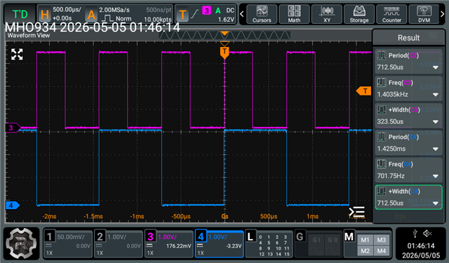
  • Attached is a screenshot of my scope. The pink trace is PA22 IO that I am toggling and represents the amount of time it takes for processing to finish. In my test function, I am just computing min/max and when the processing is complete we turn PA22 low. My ADC sample count is 2048.

    PB30 (blue trace) is toggled inside the DMA ISR. Once on early-IRQ (when the first half-buffer fills) and once on full-IRQ (when the second half fills). The square wave you see has period 1.42 ms with high/low width of 712 µs each, so each half-buffer arrives 712 µs after the previous one. I get my calculations by printing out over UART the halves processed in 500ms. I am consistently getting 694 halves processed every 500ms. So 694 halves/500ms  *  2048 samples/half = ~2.84MSPS. Let me know if there is something else you'd like to see. 

    I will attach my adc.c driver and this is the test function used to measure adc/dma performance:

    static void test_adc_dma(void)
    {
        mcu_init();
        trace_init();
        adc_init();
    
        adc_start_capture();
    
        uint32_t half_count = 0;
        uint16_t last_min = 0xFFFF; // highest value possible
        uint16_t last_max = 0;
        uint32_t last_print = millis();
    
        while (1) {
            for (uint8_t half = 0; half < 2; half++) {
                const uint16_t *buff = adc_get_samples(ADC_MODULE_0, half);
                if (buff == NULL)
                    continue;
    
                // processing data and togging io
                io_set_out(IO_DEBUG_PROC, IO_OUT_HIGH);
                uint16_t mn = 0xFFFF;
                uint16_t mx = 0;
                for (uint32_t i = 0; i < ADC_SAMPLE_COUNT; i++) {
                    if (buff[i] < mn)
                        mn = buff[i];
                    if (buff[i] > mx)
                        mx = buff[i];
                }
                io_set_out(IO_DEBUG_PROC, IO_OUT_LOW);
                last_min = mn;
                last_max = mx;
                half_count++;
            }
            if (millis() - last_print >= 500) {
                last_print = millis();
                TRACE("havles=%lu min=%u, max=%u", half_count, last_min, last_max);
            }
        }
    }
    

    #include "drivers/io.h"
    #include "drivers/adc.h"
    #include <stdbool.h>
    #include <stdint.h>
    #include <ti/driverlib/dl_hsadc.h>
    #include "common/defines.h"
    #include <ti/driverlib/dl_timera.h>
    #include <ti/driverlib/dl_dma.h>
    #include <stddef.h>
    
    #define TIMER_LOAD_VALUE (16U) // for TIMER_0
    
    static uint16_t sample_buffer[2][2][ADC_SAMPLE_COUNT]; // [module][half][samples]
    static volatile bool buffer_ready[2][2]; // [module][half]
    
    static struct
    {
        hsadc_ADC_LITE_REGS_Regs *ctrl;
        hsadc_ADC_LITE_RESULT_REGS_Regs *rslt;
    } modules[] = {
        [ADC_MODULE_0] = { ADC0_ADC_LITE_REGS, ADC0_ADC_LITE_RESULT_REGS },
        [ADC_MODULE_1] = { ADC1_ADC_LITE_REGS, ADC1_ADC_LITE_RESULT_REGS },
    };
    
    // helper function to help bring up both configs
    // for the ADC0/ADC1 at once with DMA
    static void init_hsadc(adc_module_e mod)
    {
        hsadc_ADC_LITE_REGS_Regs *adc = modules[mod].ctrl;
    
        DL_HSADC_setClockDivideRatio(adc, DL_HSADC_CLOCK_DIVIDE_1_0);
        DL_HSADC_SOCChannelSelect(adc, DL_HSADC_SOC_NUMBER0, DL_HSADC_ADCIN_0);
        DL_HSADC_SOCChannelSelect(adc, DL_HSADC_SOC_NUMBER1, DL_HSADC_ADCIN_0); // just added SOC1
        DL_HSADC_setupSequencer(adc, DL_HSADC_SEQ_NUMBER1, 16, DL_HSADC_TRIGGER_GEN_SUB_0,
                                DL_HSADC_SOC_NUMBER0);
        DL_HSADC_enableSequencer(adc, DL_HSADC_SEQ_NUMBER1);
        DL_HSADC_setSampleCapReset(adc, DL_HSADC_SEQ_NUMBER1, DL_HSADC_SAMPCAPRESET_HALF_VREFHI);
        DL_HSADC_setEndOfSequencer(adc, DL_HSADC_SOC_NUMBER1);
    
        // DMA trigger wiring on ADC side
        // SOC0 + SOC1, once every 32-bit pair of results
        DL_HSADC_DMAInterruptStatusClear(adc, DL_HSADC_DMA_INT_1);
        DL_HSADC_enableDMAContinueToInterruptMode(adc, DL_HSADC_DMA_INT_1);
        DL_HSADC_DMAInterruptSourceSelect(adc, DL_HSADC_DMA_INT_1,
                                          DL_HSADC_SOC_NUMBER1); // fire on EOC1
        DL_HSADC_enableDMAInterrupt(adc, DL_HSADC_DMA_INT_1);
    
        // Subscribe to event fabric channel 1 (timer publishes here)
        DL_HSADC_setSubscriberChanID(adc, DL_HSADC_SUBSCRIBER_INDEX_0, 1);
    
        DL_HSADC_PowerUp(adc);
    }
    
    // DMA
    static const DL_DMA_Config dma_config_adc0 = {
        .transferMode = DL_DMA_FULL_CH_REPEAT_SINGLE_TRANSFER_MODE,
        .extendedMode = DL_DMA_NORMAL_MODE,
        .destIncrement = DL_DMA_ADDR_INCREMENT,
        .srcIncrement = DL_DMA_ADDR_UNCHANGED,
        .destWidth = DL_DMA_WIDTH_WORD, // Previously tried HALF-WORD
        .srcWidth = DL_DMA_WIDTH_WORD,
        .trigger = DMA0_ADC0_TRIG1,
        .triggerType = DL_DMA_TRIGGER_TYPE_EXTERNAL,
    };
    
    static const DL_DMA_Config dma_config_adc1 = {
        .transferMode = DL_DMA_FULL_CH_REPEAT_SINGLE_TRANSFER_MODE,
        .extendedMode = DL_DMA_NORMAL_MODE,
        .destIncrement = DL_DMA_ADDR_INCREMENT,
        .srcIncrement = DL_DMA_ADDR_UNCHANGED,
        .destWidth = DL_DMA_WIDTH_WORD,
        .srcWidth = DL_DMA_WIDTH_WORD,
        .trigger = DMA0_ADC1_TRIG1,
        .triggerType = DL_DMA_TRIGGER_TYPE_EXTERNAL,
    };
    
    /* These config below are from the hsadc_max_freq example */
    // Timer A configuration for ADC
    // sourced by BUSCLK @ 160MHz
    // timerClkFreq = (timerClkSrc / (timerClkDivRatio * (timerClkPrescale + 1)))
    // 160000000 Hz = 160000000 Hz / (1 * (0 + 1))
    static const DL_TimerA_ClockConfig TIMER_0ClockConfig = {
        .clockSel = DL_TIMER_CLOCK_BUSCLK,
        .divideRatio = DL_TIMER_CLOCK_DIVIDE_1,
        .prescale = 0u,
    };
    
    /*
     * Timer load value (where the counter starts from) is calculated as (timerPeriod * timerClockFreq)
     * - 1 TIMER_0_INST_LOAD_VALUE = (106.25 ns * 160000000 Hz) - 1
     */
    static const DL_TimerA_TimerConfig TIMER_0TimerConfig = {
        .period = TIMER_LOAD_VALUE,
        .timerMode = DL_TIMER_TIMER_MODE_PERIODIC,
        .startTimer = DL_TIMER_STOP,
    };
    
    void adc_start_capture(void)
    {
        buffer_ready[ADC_MODULE_0][0] = false;
        buffer_ready[ADC_MODULE_0][1] = false;
        buffer_ready[ADC_MODULE_1][0] = false;
        buffer_ready[ADC_MODULE_1][1] = false;
    
        // DMA CH0: ADC0 result register goes to sample_buffer[0]
        DL_DMA_setSrcAddr(DMA0, 0,
                          (uint32_t)&modules[ADC_MODULE_0].rslt->ADC_LITE_RESULT_REGS.ADCRESULT0);
        DL_DMA_setDestAddr(DMA0, 0, (uint32_t)sample_buffer[ADC_MODULE_0]);
        DL_DMA_setTransferSize(DMA0, 0, ADC_SAMPLE_COUNT);
        DL_DMA_enableChannel(DMA0, 0);
    
        // DMA CH1 : ADC1 result register goes to sample_buffer[1]
        DL_DMA_setSrcAddr(DMA0, 1,
                          (uint32_t)&modules[ADC_MODULE_1].rslt->ADC_LITE_RESULT_REGS.ADCRESULT0);
        DL_DMA_setDestAddr(DMA0, 1, (uint32_t)sample_buffer[ADC_MODULE_1]);
        DL_DMA_setTransferSize(DMA0, 1, ADC_SAMPLE_COUNT);
        DL_DMA_enableChannel(DMA0, 1);
    
        // Enanle timer
        DL_TimerA_startCounter(TIMA0_0);
    }
    
    void adc_stop_capture(void)
    {
        DL_TimerA_stopCounter(TIMA0_0);
    }
    
    // check flag, return buffer or NULL
    const uint16_t *adc_get_samples(adc_module_e adc, uint8_t half)
    {
        if (!buffer_ready[adc][half])
            return NULL;
        buffer_ready[adc][half] = false; // acknowledges we got the data, reset signal
        return sample_buffer[adc][half];
    }
    
    void adc_init(void)
    {
    
        DL_HSADC_reset(modules[ADC_MODULE_0].ctrl); // reset ADC0
        DL_HSADC_reset(modules[ADC_MODULE_1].ctrl); // reset ADC1
        DL_TimerA_reset(TIMA0_0); // reset timer
    
        DL_HSADC_enablePower(modules[ADC_MODULE_0].ctrl); // enable power for both ADCs
        DL_HSADC_enablePower(modules[ADC_MODULE_1].ctrl);
        DL_TimerA_enablePower(TIMA0_0);
        BUSY_WAIT_CYCLES(4); // 4 CPU cycles
    
        // get both ADC configs in one go
        init_hsadc(ADC_MODULE_0);
        init_hsadc(ADC_MODULE_1);
    
        // // Timer
        DL_TimerA_setClockConfig(TIMA0_0, &TIMER_0ClockConfig);
        DL_TimerA_initTimerMode(TIMA0_0, &TIMER_0TimerConfig);
        DL_TimerA_enableClock(TIMA0_0);
        DL_TimerA_enableEvent(TIMA0_0, DL_TIMERA_EVENT_ROUTE_1, DL_TIMERA_EVENT_ZERO_EVENT);
        DL_TimerA_setPublisherChanID(TIMA0_0, DL_TIMERA_PUBLISHER_INDEX_0, 1);
    
        // DMA INIT
        DL_DMA_initChannel(DMA0, 0, &dma_config_adc0);
        DL_DMA_initChannel(DMA0, 1, &dma_config_adc1);
    
        DL_DMA_Full_Ch_setEarlyInterruptThreshold(DMA0, 0, DL_DMA_EARLY_INTERRUPT_THRESHOLD_HALF);
        DL_DMA_Full_Ch_setEarlyInterruptThreshold(DMA0, 1, DL_DMA_EARLY_INTERRUPT_THRESHOLD_HALF);
    
        // enable DMA Interrupts
        DL_DMA_enableInterrupt(DMA0, DL_DMA_INTERRUPT_CHANNEL0);
        DL_DMA_enableInterrupt(DMA0, DL_DMA_INTERRUPT_CHANNEL1);
        NVIC_EnableIRQ(DMA0_INT_IRQn);
    
        BUSY_WAIT_ms(1);
    }
    
    // used only for test function
    uint16_t adc_read_channel(adc_module_e adc, uint8_t channel)
    {
        hsadc_ADC_LITE_REGS_Regs *ctrl = modules[adc].ctrl;
        hsadc_ADC_LITE_RESULT_REGS_Regs *rslt = modules[adc].rslt;
    
        // select requested channel on SOC0
        DL_HSADC_SOCChannelSelect(ctrl, DL_HSADC_SOC_NUMBER0,
                                  (DL_HSADC_ADCIN)channel); // cast int into an enum
    
        // software force to start conversion
        DL_HSADC_triggerSequencerSoftwareForce(ctrl, DL_HSADC_SEQ_NUMBER1);
    
        // poll until conversion is complete
        // returns false if ADC is available to sample next channel
        while (DL_HSADC_isBusy(ctrl))
            ;
    
        // read and return 12bit result
        return DL_HSADC_getResult(rslt, DL_HSADC_SOC_NUMBER0);
    }
    // DEBUG_PROC measures how long the main loop spends processing a half
    // DEBUG_ISR measures when does the DMA hardware signal half complete, raw hardware timing
    void DMA0_IRQHandler(void)
    {
        switch (DL_DMA_getPendingInterrupt(DMA0)) {
        case DL_DMA_FULL_CH_EVENT_IIDX_EARLY_IRQ_DMACH0:
            buffer_ready[ADC_MODULE_0][0] = true; // first half full
            io_toggle(IO_DEBUG_ISR); // toggles when timing for first half of DMA complete
            break;
        case DL_DMA_EVENT_IIDX_DMACH0:
            buffer_ready[ADC_MODULE_0][1] = true; // second half full. auto wrap
            io_toggle(IO_DEBUG_ISR); // toggles when timing for second half of DMA is complete
            break;
        case DL_DMA_FULL_CH_EVENT_IIDX_EARLY_IRQ_DMACH1:
            buffer_ready[ADC_MODULE_1][0] = true;
            io_toggle(IO_DEBUG_ISR);
            break;
        case DL_DMA_EVENT_IIDX_DMACH1:
            buffer_ready[ADC_MODULE_1][1] = true;
            io_toggle(IO_DEBUG_ISR);
            break;
        default:
            break;
        }
    }


  • Hi Eric,

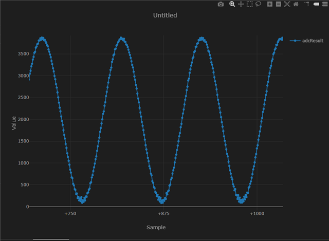
    Sorry I missed the second half of your previous message but I am using a wave form generator to feed in a sine wave at a known frequency (94 Khz). At this frequency I'd expect 100 samples between the two peaks. 

  • Thanks for showing your plot for the 94kHz/100 samples per period. I was able to get both HSADC0/HSADC1 to simultaneously sample at a rate of ~5.7MSPS which I believe matches with what you initially saw on your previous run. I am using SOC0/SOC1 with sampleWindow=16, ACQPS =15.
    I used TIMG4_0 to trigger the sequencer for both ADCs since I found the errata sheet says TIMA_0 does not work with multiple events (TIMER_ERR_08). 

    I then decided to try to run the example project in CCS the same way you have with using SOC0/SOC1 and feeding in a 94kHz sine wave. And the sampling rate I see from using the example seems odd but consistent with whether or not I use half word widths or words widths with DMA. I will share the ti_msp_dl_config.c and main.c of this example project along with the graph. I feel that I am missing some configuration that you are using in your ti_msp_dl_config.c. But I can confirm that I can have simultaneous ADCs working.

  • Hi Eric,

    There's a known bug in this example where the DMA is in block mode not Single mode. I believe if you make this adjustment it should fix it.

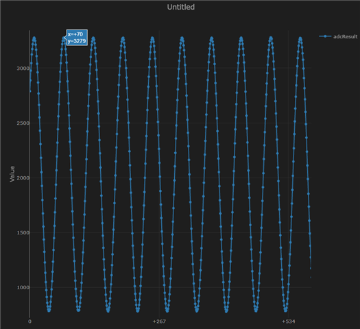
  • I have switched the .transferMode to DL_DMA_SINGLE_TRANSFER_MODE and I am currently using SOC0/SOC1. My sequencer is configured the same way the example does by default and yet after feeding the PA27 with a known 94kHz sine wave I am unable to replicate your plot. This is what my plot currently looks like and I will also show my ti_msp_dl_config.c. I am seeing ~5.7MSPS with this example project. I also see 5.7MSPS sampling rate with my project regarding ping pong continuous streaming. Each peak is ~61 samples/cycle so unless there is another configuration I am missing I don't know how my config differs from yours.

    #include "ti_msp_dl_config.h"
    
    DL_TimerA_backupConfig gTIMER_0Backup;
    
    /*
     *  ======== SYSCFG_DL_init ========
     *  Perform any initialization needed before using any board APIs
     */
    SYSCONFIG_WEAK void SYSCFG_DL_init(void)
    {
        SYSCFG_DL_initPower();
        SYSCFG_DL_GPIO_init();
        /* Module-Specific Initializations*/
        SYSCFG_DL_SYSCTL_init();
        SYSCFG_DL_TIMER_0_init();
        SYSCFG_DL_HSADC0_init();
        SYSCFG_DL_DMA0_init();
        /* Ensure backup structures have no valid state */
    	gTIMER_0Backup.backupRdy 	= false;
    
    }
    /*
     * User should take care to save and restore register configuration in application.
     * See Retention Configuration section for more details.
     */
    SYSCONFIG_WEAK bool SYSCFG_DL_saveConfiguration(void)
    {
        bool retStatus = true;
    
    	retStatus &= DL_TimerA_saveConfiguration(TIMER_0_INST, &gTIMER_0Backup);
    
        return retStatus;
    }
    
    
    SYSCONFIG_WEAK bool SYSCFG_DL_restoreConfiguration(void)
    {
        bool retStatus = true;
    
    	retStatus &= DL_TimerA_restoreConfiguration(TIMER_0_INST, &gTIMER_0Backup, false);
    
        return retStatus;
    }
    
    SYSCONFIG_WEAK void SYSCFG_DL_initPower(void)
    {
        DL_GPIO_reset(GPIOA);
        DL_TimerA_reset(TIMER_0_INST);
        DL_HSADC_reset(HSADC0_INST);


        DL_GPIO_enablePower(GPIOA);
        DL_TimerA_enablePower(TIMER_0_INST);
        DL_HSADC_enablePower(HSADC0_INST);
    
        delay_cycles(POWER_STARTUP_DELAY);
    }
    
    SYSCONFIG_WEAK void SYSCFG_DL_GPIO_init(void)
    {
    
    }
    
    
    static const DL_SYSCTL_SYSPLLConfig gSYSPLLConfig = {
        .inputFreq              = DL_SYSCTL_SYSPLL_INPUT_FREQ_32_48_MHZ,
    	.rDivClk2x              = 1,
    	.rDivClk1               = 0,
    	.rDivClk0               = 0,
    	.enableCLK2x            = DL_SYSCTL_SYSPLL_CLK2X_ENABLE,
    	.enableCLK1             = DL_SYSCTL_SYSPLL_CLK1_DISABLE,
    	.enableCLK0             = DL_SYSCTL_SYSPLL_CLK0_ENABLE,
    	.sysPLLMCLK             = DL_SYSCTL_SYSPLL_MCLK_CLK0,
    	.sysPLLRef              = DL_SYSCTL_SYSPLL_REF_SYSOSC,
    	.qDiv                   = 9,
    	.pDiv                   = DL_SYSCTL_SYSPLL_PDIV_1
    };
    
    SYSCONFIG_WEAK bool SYSCFG_DL_SYSCTL_SYSPLL_init(void)
    {
        bool fFCCRatioStatus = false;
        uint32_t fFCCSysoscCount;
        uint32_t fFCCPllCount;
        uint32_t fFCCRatio;
    
        DL_SYSCTL_setFCCPeriods( DL_SYSCTL_FCC_TRIG_CNT_01 );
    
        //Measuring PLL. Use ONLY this configuration. DO NOT EDIT
        DL_SYSCTL_configFCC(DL_SYSCTL_FCC_TRIG_TYPE_RISE_RISE,
                            DL_SYSCTL_FCC_TRIG_SOURCE_LFCLK,
                            DL_SYSCTL_FCC_CLOCK_SOURCE_SYSPLLCLK0);
        /* Get SYSPLL frequency using FCC */
        DL_SYSCTL_startFCC();
        while (DL_SYSCTL_isFCCDone() == 0);
    
        /* get measA= SYSPLL0 freq wrt LFOSC*/
        fFCCPllCount = DL_SYSCTL_readFCC();
    
        //Measuring SYSPLL Source
        DL_SYSCTL_configFCC(DL_SYSCTL_FCC_TRIG_TYPE_RISE_RISE,
                            DL_SYSCTL_FCC_TRIG_SOURCE_LFCLK,
                            DL_SYSCTL_FCC_CLOCK_SOURCE_SYSOSC);
        /* Get SYSPLL frequency using FCC */
        DL_SYSCTL_startFCC();
        while (DL_SYSCTL_isFCCDone() == 0 );//
    
        /* get measB= SYSOSC freq wrt LFOSC*/
        fFCCSysoscCount = DL_SYSCTL_readFCC();
    
        /* Get ratio of both measurements*/
        fFCCRatio = (fFCCPllCount * FLOAT_TO_INT_SCALE) / fFCCSysoscCount;
        /* Check ratio is within bounds*/
        if ((FCC_LOWER_BOUND <  fFCCRatio) && (fFCCRatio < FCC_UPPER_BOUND))
        {
            fFCCRatioStatus = true; //ratio is good for proceeding into application code.
        }
    
        return fFCCRatioStatus;
    }
    SYSCONFIG_WEAK void SYSCFG_DL_SYSCTL_init(void)
    {
    
    	//Low Power Mode is configured to be SLEEP
        DL_SYSCTL_setBORThreshold(DL_SYSCTL_BOR_THRESHOLD_LEVEL_0);
    
        
    	DL_SYSCTL_setSYSOSCFreq(DL_SYSCTL_SYSOSC_FREQ_BASE);
        DL_SYSCTL_configSYSPLL((DL_SYSCTL_SYSPLLConfig *) &gSYSPLLConfig);
    
        /*
         * PLL Incorrect locking WA start.
         * Insert after every PLL enable.
         * This can lead an infinite loop if the condition persists
         * and can block entry to the application code.
         */
    
        while (SYSCFG_DL_SYSCTL_SYSPLL_init() == false)
        {
            /* Toggle SYSPLL enable to re-enable SYSPLL and re-check incorrect locking */
            DL_SYSCTL_disableSYSPLL();
            DL_SYSCTL_enableSYSPLL();
    
            /* Wait until SYSPLL startup is stabilized*/
            while ((DL_SYSCTL_getClockStatus() & SYSCTL_CLKSTATUS_SYSPLLGOOD_MASK) != DL_SYSCTL_CLK_STATUS_SYSPLL_GOOD){}
        }
        DL_SYSCTL_disablePLLDivider( );
        DL_SYSCTL_setMCLKSource(SYSOSC, HSCLK, DL_SYSCTL_HSCLK_SOURCE_SYSPLL);
        DL_SYSCTL_setHSCLKSource(DL_SYSCTL_HSCLK_SOURCE_SYSPLL);
    
    
    }


    /*
     * Timer clock configuration to be sourced by BUSCLK (160000000 Hz)
     * timerClkFreq = (timerClkSrc / (timerClkDivRatio * (timerClkPrescale + 1)))
     *   160000000 Hz = 160000000 Hz / (1 * (0 + 1))
    */
    static const DL_TimerA_ClockConfig gTIMER_0ClockConfig = {
        .clockSel    = DL_TIMER_CLOCK_BUSCLK,
        .divideRatio = DL_TIMER_CLOCK_DIVIDE_1,
        .prescale    = 0U,
    };
    
    /*
     * Timer load value (where the counter starts from) is calculated as (timerPeriod * timerClockFreq) - 1
     * TIMER_0_INST_LOAD_VALUE = (106.25 ns * 160000000 Hz) - 1
     */
    static const DL_TimerA_TimerConfig gTIMER_0TimerConfig = {
        .period     = TIMER_0_INST_LOAD_VALUE,
        .timerMode  = DL_TIMER_TIMER_MODE_PERIODIC,
        .startTimer = DL_TIMER_STOP,
    };
    
    SYSCONFIG_WEAK void SYSCFG_DL_TIMER_0_init(void) {
    
        DL_TimerA_setClockConfig(TIMER_0_INST,
            (DL_TimerA_ClockConfig *) &gTIMER_0ClockConfig);
    
        DL_TimerA_initTimerMode(TIMER_0_INST,
            (DL_TimerA_TimerConfig *) &gTIMER_0TimerConfig);
        DL_TimerA_enableClock(TIMER_0_INST);
    
    
        DL_TimerA_enableEvent(TIMER_0_INST, DL_TIMERA_EVENT_ROUTE_1, (DL_TIMERA_EVENT_ZERO_EVENT));
    
        DL_TimerA_setPublisherChanID(TIMER_0_INST, DL_TIMERA_PUBLISHER_INDEX_0, TIMER_0_INST_PUB_0_CH);


    }


    SYSCONFIG_WEAK void SYSCFG_DL_HSADC0_init(void)
    {
        DL_HSADC_setClockDivideRatio(HSADC0_INST,DL_HSADC_CLOCK_DIVIDE_1_0);
    
        DL_HSADC_SOCChannelSelect(HSADC0_INST, DL_HSADC_SOC_NUMBER0, DL_HSADC_ADCIN_0);
        DL_HSADC_SOCChannelSelect(HSADC0_INST, DL_HSADC_SOC_NUMBER1, DL_HSADC_ADCIN_0);
    
        DL_HSADC_setupSequencer(HSADC0_INST, DL_HSADC_SEQ_NUMBER1, 16, DL_HSADC_TRIGGER_GEN_SUB_0, DL_HSADC_SOC_NUMBER0);
        DL_HSADC_enableSequencer(HSADC0_INST, DL_HSADC_SEQ_NUMBER1);
        DL_HSADC_setSampleCapReset(HSADC0_INST, DL_HSADC_SEQ_NUMBER1, DL_HSADC_SAMPCAPRESET_HALF_VREFHI);
        DL_HSADC_setEndOfSequencer(HSADC0_INST, DL_HSADC_SOC_NUMBER1);
    
    
        DL_HSADC_DMAInterruptStatusClear(HSADC0_INST, DL_HSADC_DMA_INT_1);
        DL_HSADC_enableDMAContinueToInterruptMode(HSADC0_INST, DL_HSADC_DMA_INT_1);
        DL_HSADC_DMAInterruptSourceSelect(HSADC0_INST, DL_HSADC_DMA_INT_1, DL_HSADC_SOC_NUMBER1);
        DL_HSADC_enableDMAInterrupt(HSADC0_INST, DL_HSADC_DMA_INT_1);
        DL_HSADC_SetInterruptPulsePosition(HSADC0_INST, DL_HSADC_INT_PULSE_POS_EOC);
    
    
        DL_HSADC_setSubscriberChanID(HSADC0_INST, DL_HSADC_SUBSCRIBER_INDEX_0, 1);
        DL_HSADC_PowerUp(HSADC0_INST);
    }
    
    
    static const DL_DMA_Config gDMA0_CH0Config = {
        .transferMode   = DL_DMA_SINGLE_TRANSFER_MODE,
        .extendedMode   = DL_DMA_NORMAL_MODE,
        .destIncrement  = DL_DMA_ADDR_INCREMENT,
        .srcIncrement   = DL_DMA_ADDR_UNCHANGED,
        .destWidth      = DL_DMA_WIDTH_WORD,
        .srcWidth       = DL_DMA_WIDTH_WORD,
        .trigger        = DMA0_CH0_TRIGGER_SEL_ADC0,
        .triggerType    = DL_DMA_TRIGGER_TYPE_EXTERNAL,
    };
    
    SYSCONFIG_WEAK void SYSCFG_DL_DMA0_CH0_init(void)
    {
    
        DL_DMA_setDestIncrement(DMA0, DMA0_CH0_CHAN_ID, DL_DMA_ADDR_INCREMENT);
        DL_DMA_initChannel(DMA0, DMA0_CH0_CHAN_ID , (DL_DMA_Config *) &gDMA0_CH0Config);
    }
    SYSCONFIG_WEAK void SYSCFG_DL_DMA0_init(void){
        SYSCFG_DL_DMA0_CH0_init();
    }


  • Hi Eric,

    Sorry i was OOO. I believe I attached the sysconfig and .c file in a previous message which gave me the results shared. Please let me know if using those files you cannot recreate the waveform.

  • Also make sure to have the DMA transfer size for 32 bits either by increasing the Source size or doubling the DMA transfer size when you call it in your applicaiton. The reason for this is to get the result for both soc0 and soc1.