This thread has been locked.

If you have a related question, please click the "Ask a related question" button in the top right corner. The newly created question will be automatically linked to this question.

AM263P4-Q1: I wanted to Enable the ePWM Clock

Part Number: AM263P4-Q1
Other Parts Discussed in Thread: SYSCONFIG, TIDM-02018

Hi,

I am working on AM263Px microcontroller, I would like to enable the ePWM clock and how to configure the CONTROLSS registers (LOCK0_KICK0, LOCK0_KICK1) before enabling ePWM clcok. Please explain the workflow in detail. I am grateful to your suggestions and help.

Thank you !

Regards,

Rajkumar

  • Here's the detailed step-by-step workflow for unlocking the CONTROLSS registers and enabling the ePWM clock on your AM263P4-Q1.

    All Control Module MMRs (Memory-Mapped Registers) on the AM263Px have a kick protection mechanism that prevents spurious writes from changing register values. You must unlock these registers before configuring ePWM clocks, and re-lock them afterward.

    Step 1: Unlock CONTROLSS_CTRL Registers

    Write the exact unlock values in sequence to the KICK registers:

    Register
    Address
    Unlock Value
    CONTROLSS_CTRL_LOCK0_KICK0
    0x502F1008
    0x01234567
    CONTROLSS_CTRL_LOCK0_KICK1
    0x502F100C
    0x0FEDCBA8

    Order matters — write KICK0 first, then KICK1.

    /* Unlock CONTROLSS_CTRL registers */
    *((volatile uint32_t *)0x502F1008) = 0x01234567; // LOCK0_KICK0
    *((volatile uint32_t *)0x502F100C) = 0x0FEDCBA8; // LOCK0_KICK1
    Important: Writing any value other than the exact unlock keys will re-lock the registers .

    Step 2: Disable ePWM Time-Base Clock (TBCLK) Synchronization

    Before configuring ePWM modules, clear the EPWM_CLKSYNC bit for the corresponding ePWM instance(s) in the CONTROLSS_CTRL register:

    /* Set EPWM_CLKSYNC bit = 0 for the target ePWM instance */
    SOC_setEpwmTbClk(epwmInstance, FALSE);

    Step 3: Configure Your ePWM Module(s)

    Perform all ePWM configuration (time-base period, counter mode, action qualifiers, deadband, etc.) while the clock sync is disabled.

    Step 4: Enable ePWM Time-Base Clock Synchronization

    After configuration is complete, set the EPWM_CLKSYNC bit = 1. This globally synchronizes all enabled ePWM module clocks with the first rising edge of TBCLK:

    /* Enable TBCLK for the target ePWM instance */
    SOC_setEpwmTbClk(epwmInstance, TRUE);
    /* Or enable multiple instances at once */
    SOC_setMultipleEpwmTbClk(instanceBitMask, TRUE);

    Step 5: (Optional) Ungate ePWM Clock

    If clock gating is used for power management, call:

    SOC_ungateEpwmClock(epwmInstance);
    Step 6: Re-Lock CONTROLSS_CTRL Registers

    After all configuration is complete, always re-lock the registers to prevent accidental modification:

    /* Lock CONTROLSS_CTRL registers */
    *((volatile uint32_t *)0x502F100C) = 0x00000000; // LOCK0_KICK1 first
    *((volatile uint32_t *)0x502F1008) = 0x00000000; // LOCK0_KICK0 second

    Using SysConfig (Recommended)

    If you're using the MCU+ SDK with SysConfig, this entire unlock → configure → lock sequence is auto-generated in ti_drivers_open_close.c when you add an ePWM instance through the GUI. This eliminates the need for manual register writes.

    Best Regards,

    Masoud

  • Thank you, Masoud, for your response and detailed explanation.

    I implemented based on the given steps.

    Step 1: Unlock CONTROLSS_CTRL Registers

    HWREG32(CONTROLSS_CTRL_BASE + LOCK0_KICK0) = 0x01234567U;

    HWREG32(CONTROLSS_CTRL_BASE + LOCK0_KICK1) = 0xFEDCBA89U;

    Step 2: Enable ePWM Clock (EPWM clock)

     HWREG32(CONTROLSS_CTRL_BASE + EPWM0_CLK_GATE) = 0x0U;

    First, I enabled the ePWM clock before enabling the TBCLK. Please confirm whether this step is correct or not 

    Step 3: Disable ePWM Time-Base Clock (TBCLK) Synchronization

     HWREG32(CONTROLSS_CTRL_BASE + EPWM0_CLK_SYNC) = (0U << 0);


    Step 4: Configured  ePWM Module

    HWREG16(EPWM0_BASE + EPWM_TBCTL)  =  (2U << 0); // using up-down count 


    Step 5: Enable ePWM Time-Base Clock Synchronization


       HWREG32(CONTROLSS_CTRL_BASE + EPWM0_CLK_SYNC) |= (1U << 0);


    Step 6: Lock CONTROLSS_CTRL Registers

    HWREG32(CONTROLSS_CTRL_BASE + LOCK0_KICK1) = 0x0U;

    HWREG32(CONTROLSS_CTRL_BASE + LOCK0_KICK0) = 0x0U;

     After compilation, the ePWM clock was not enabled, which means the "1" value is not stored in the CONTROLSS_CTRL_BASE + EPWM0_CLK_SYNC register

     Please check and revert to me.

    Thank you!

     Regards,

    Rajkumar

  • Your overall sequence is correct, but there is issue that is likely preventing the ePWM clock from enabling properly. In Step 5, you use a bitwise OR

    HWREG32(CONTROLSS_CTRL_BASE + EPWM0_CLK_SYNC) |= (1U << 0);

    If the register wasn't previously cleared or if the read-back returns an unexpected value, this OR operation may not reliably set the bit. Use a direct assignment instead:

    HWREG32(CONTROLSS_CTRL_BASE + EPWM0_CLK_SYNC) = (1U << 0);

    Overall, the recommended approach is to use SDK APIs. Rather than direct register writes, the MCU+ SDK provides dedicated functions that handle the unlock/lock sequence and correct register values internally:

    /* Enable ePWM clock (ungate) */
    SOC_ungateEpwmClock(0);  // For EPWM0 instance
    
    /* Disable TBCLK before configuration */
    SOC_setEpwmTbClk(0, FALSE);
    
    /* Configure ePWM module */
    HWREG16(EPWM0_BASE + EPWM_TBCTL) = (2U << 0);
    
    /* Enable TBCLK after configuration */
    SOC_setEpwmTbClk(0, TRUE);

    Best Regards,

    Masoud

  • Thank you, Masoud, for the immediate response.

    I modified according to your input, but the ePWM clock was still not enabled.

    I am developing Baremetal code considering Syscfg. What are the libraries that need to be disabled? Please let me know.

    Thank you !

    Regards,

    Rajkumar

  • Hi,

    If you are using SysConfig, the SOC clock configuration is generally handled by the generated code, so please make sure the ePWM instance is enabled/configured in SysConfig and that the generated initialization code is being called before accessing the ePWM registers. That would be all.

    If you want to check the register level, the ePWM time-base clock should be enabled using the SOC API:

    SOC_setEpwmTbClk(epwmInstance, TRUE);

    This API is available in:

    source/drivers/soc/am263px/soc.c

    That would give the idea how API enabling it.

    Regards,

    Masoud

  • Hi Masoud,

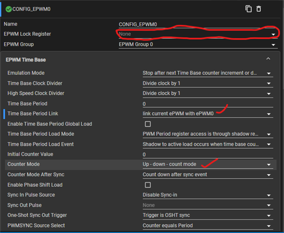
    I have done the configurations in Sysconfg for enabling the ePWM instance. I configured in Time Base and attached the screenshots, which I enabled. If anything is missed, please let me know. 

    Regards,

    Rajkumar

  • Hi Rajkumar,

    The SysConfig settings you shared look fine for adding/configuring the EPWM instance. Can you confirm the SysConfig generated initialization code is actually called? For SysConfig-based bare-metal projects, the generated clock/pinmux/peripheral initialization is applied only when the generated init functions are called from the application. For example:

    System_init();
    Board_init();
    
    Drivers_open();
    Board_driversOpen();

    From the screenshot, the Time Base Period is set to 0. Even if the EPWM clock is enabled, you will not get a meaningful PWM waveform with TBPRD = 0. Please set a non-zero period value, and also configure CMPA/CMPB and Action Qualifier settings if you want to observe EPWM output on the pin.

    If the register still does not retain the value, it usually means either the CONTROLSS registers are still locked, the generated initialization is not being called, or another part of the code is disabling TBCLK again.

    I would suggest starting from an existing AM263Px SDK EPWM example, enable EPWM0 in SysConfig, and then compare the generated files and application init sequence with your bare-metal project.

    Best Regards,

    Masoud

  • Hi Masoud,

    Now, I am enabling the ePWM clock, but facing the issue at ADCINTFLG (the interrupt was not generating)

    I am developing the bare-metal code for the ADC trigger by ePWM. The following workflow is given below.

     1  Enable EPWM clock
     2. Enable ADC clock
     3. Enable ADC reference
     4. Configure ADC input range
     5. Power up ADC core
     6. Initialize ADC configuration
     7. Configure ADC interrupt
    *8. ADC Triggered by ePWM
    I configured ePWM by using ETSEL and ETPS registers     
    HWREG16(EPWM0_BASE + EPWM_ETSEL)  =  (1U << 11) | (1U << 8);
    HWREG16(EPWM0_BASE + EPWM_ETPS)  =  (1U << 8);  
    If any ePWM register is missed, please let me know
      *9. ADC interrupt occurs
         
      while ((HWREG16(ADC_BASE + ADCINTFLG) & (1U << 0)) == 0U)   // Facing the issue at this line. I'm stuck in a while loop, it's not come out of the loop.
       {
          /* Wait for End of conversion */
       }
       HWREG16(ADC_BASE + ADCINTFLGCLR) = (1U << 0);
      *10. ADC_ReadPhaseCurrents

       Please check and let me know if any mistakes are there.

       Thank you!

       Regards,

       Rajkumar

  • Please refer to our example in "https://www.ti.com/tool/TIDM-02018". the software is available in MOTOR-CONTROL-SDK-AM263X "https://www.ti.com/tool/download/MOTOR-CONTROL-SDK-AM263X/09.00.00.06". the routine you're mentioning here is implemented in that reference design.

    Best Regards,

    Masoud