Part Number: MSPM0C1103
Other Parts Discussed in Thread: MSPM0L1304, , UNIFLASH, SYSCONFIG
Hi,
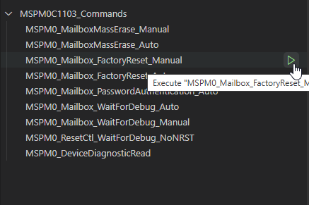
1- In a 16 pin MSPM0C1103SDYYR, I decided to use pin 12 SWCLK as digital input after programming, but it locks me out (somehow microcontroller goes into bricking mode). I cannot perform reset factory. Please provide a set of instruction to resolve such issue.
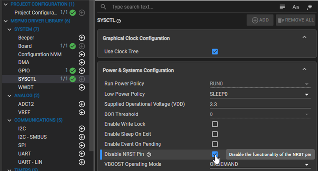
2- In a 16 pin MSPM0C1103SDYYR, I used pins 3 as SDA and pin 4 (NRST pin as well) as SCL for I2C communication with pins 4 as SDA and pin 5 (NRST pin as well) as SCL of a 20 pin MSPM0L1304TDGS20R microcontroller. I connected 4.7k Ohm as pull up for SDA and SCL.
Warning for MSPM0L1304:
Error and warning for MSPM0C1103:

a) Any collision or conflict to use SCL on NRST pin on MSPM0C1103 and MSPM0L1304?
b) can I connect a 10nF capacitor to ground for reset pin still?
c) or hardware reset is not possible at power up and I should remove that 10nF to SCL/NRST pin, and software reset should be performed?
d) Is it possible to program MSPM0L1304 through MSPM0C1103 using I2C and Flash-based secondary bootloader (BSL)?
e) Any example code or document or instruction for such BSL?
3- Since MSPM0C1103 does not come with a permanent ROM-based bootloader like the larger MSPM0L or MSPM0G families, I decided to use UART (pins 9-10) to flash MSPM0C1103. I must first program a Flash-based secondary bootloader (BSL) into the device memory. I am aware that I still need to use SWD (pins 11 and 12) at least once to install this custom bootloader initially. I did, and I fell into bricking mode of MSPMOC1103 mentioned in item 1 above.
Thanks in advance,
Kind regards,