Part Number: AM13E23019
Other Parts Discussed in Thread: SYSCONFIG
Hello there
I am observing an issue with the ECAP module capture counts and have attached a project that demonstrates the behavior.
In this project:
-
The PWM frequency is configured to 16 kHz without any prescaler.
-
MCPWM is generating the SyncOut pulse for ECAP.
-
PWM1A is configured to:
Go high on Compare A
Go low on Compare B
I am observing an offset in the capture counts. Please have a look at the image from the watch window

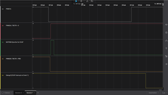
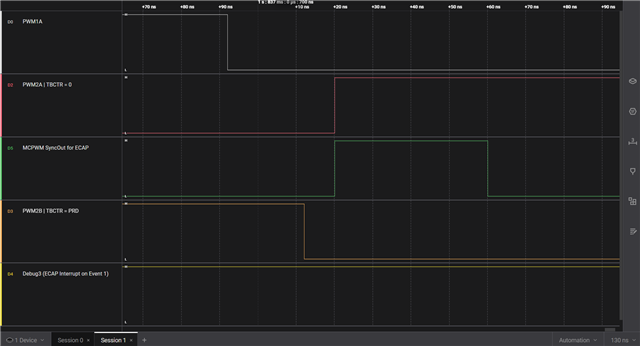
It appears that when the pulse width approaches the PWM period, the ECAP counter restarts, even though the PWM pulse width is still shorter than the configured period and Sync Out is still not generated. I have attached the Logic analyzer capture with the measurements along with Watch window when the PWM Low pulse generated is almost near to the PWM period.


Could you please help verify whether this is expected behavior or if there might be any issue in the ECAP synchronization/capture handling?