AM2612: Maximum OSPI0 clock output keeps 7.5MHz

Part Number: AM2612
Other Parts Discussed in Thread: TIDA-010979, SYSCONFIG, LP-AM261, UNIFLASH

Hi Experts,

We used same design including AM2612 and flash (ISSI IS25LP016) in TIDA-010979,  which interface is OSPI0 .

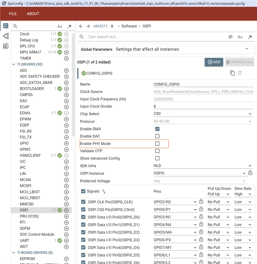
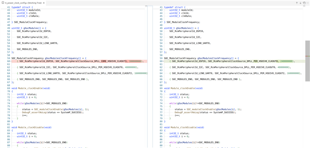
Currently we can successfully access the flash at low clock frequency(about 2MHz). Next we would like to higher it. In SYSCONFIG file, for OSPI configuration, whenever the input clock frequency(Hz) is 240000000 (240MHz), and input clock divider is either 8 or 4, the clock measured is always 7.5MHz (expect it's supposed to be 30MHz or 60MHz). Even we tried to use OSPI_setBaudRateDiv(ospiHandle, 8 or 4 or 2) API to enforce setting again after Board_flashOpen() and it keeps the same.

Could you please kindly help check and provide your suggestion? Thanks.

BR, Robert Huang 

  • Hi Robert,

    Can you please tell me which SDK (MCU PLUS SDK version) are you using? 

    Thanks,

    Aswin

  • Hi Aswin,

    It's mcu_plus_sdk_am261x_11_01_00_19 folder name.

    BR, Robert Huang

  • Hi Robert, 

    Can you please share me how the clock configuration clock configuration.

    A screen shot of the OSPI Sysconfig configuration and the OSPI Clock configuration from clock tree would be enough. I wanted to see what are the 

    PLL dividers, GM CLK dividers, and the baud rate divider.

    Thanks & Regards,

    Aswin 

  • Hi Aswin,

    Please see attached snapshot. Don't know what dimension means while Insert -> Image/Video/File and I key in the original snapshot size for each. Hopefully you can check them out clearly. Thanks.

    BR, Robert Huang

  • Hi Robert, 

    Please try this configuration.

    PLL configs are done from SBL. So in your SBL, here I have taken this project as sbl: examples\drivers\boot\sbl_ospi_multicore_elf\am261x-som

    1. Configuration in Clock tree tool

    2. Configuration in OSPI Section. Turn OFF PHY

    Do the same process in application as well. Both the clock tree and OSPI PHY configuration

    In application, the PLL configuration is necessary because based on its inputs, the application also verifies if the PLL configuration made in SBL matches with what that is configured.

    I am attaching my sysconfigs

    1. SBL Sysconfig: examples\drivers\boot\sbl_ospi_multicore_elf\am261x-som

    https://e2e.ti.com/cfs-file/__key/communityserver-discussions-components-files/908/8270.example.syscfg

    2. Application Sysconfig: examples\hello_world\am261x-som\r5fss0-0_freertos

    https://e2e.ti.com/cfs-file/__key/communityserver-discussions-components-files/908/8270.example.syscfg

    This is the output obtained. Boot media clock is 30MHz which is OSPI clock.

    Thanks & Regards,

    Aswin

  • Hi Aswin,

    I used sbl_ospi_multicore_elf_am261x-lp_r5fss0-0_nortos_ti-arm-clang project as my custom board project and made some changes as your mention as below git snapshot (before versus after). The boot media clock changed to 30MHz as yours but the waveform measured at opsi clock pin still keeps about 7.5MHz square waveform. Could you please kindly help check any possibilities? Thanks.

  • Hi Robert, 


    Can you please provide me the value of these registers.

    Thanks & Regards,

    Aswin

  • Hi Robert, 

    To clarify if these registers are configured correctly then the OSPI output freq should be 30Hz. So we can check these registers to ensure if they are configured correctly.

  • Hi Aswin, 

    We flashed 30MHz setting configuration + Disable PHY mode on both SBL and application and running output message as below for your reference.

    starting OSPI Bootloader ...
    KPI_DATA: [BOOTLOADER_PROFILE] CPU Clock : 500.000 MHz
    KPI_DATA: [BOOTLOADER_PROFILE] Boot Media : NOR SPI FLASH
    KPI_DATA: [BOOTLOADER_PROFILE] Boot Media Clock : 30.000 MHz
    KPI_DATA: [BOOTLOADER_PROFILE] Boot Image Size : 258 KB
    KPI_DATA: [BOOTLOADER_PROFILE] Cores present :
    r5f0-0
    KPI_DATA: [BOOTLOADER PROFILE] System_init : 985us
    KPI_DATA: [BOOTLOADER PROFILE] Drivers_open : 249us
    KPI_DATA: [BOOTLOADER PROFILE] LoadHsmRtFw : 6317us
    KPI_DATA: [BOOTLOADER PROFILE] Board_driversOpen : 666us
    KPI_DATA: [BOOTLOADER PROFILE] CPU load : 25770us
    KPI_DATA: [BOOTLOADER PROFILE] SBL End : 11us
    KPI_DATA: [BOOTLOADER_PROFILE] SBL Total Time Taken : 34001us

    Image loading done, switching to application ...
    [OSPI0 Clock Register Dump] Robert Huang 20260603
    ============================================================
    1. TOP_RCM_PLL_CORE_M2NDIV [0x53200410] = 0x00010009
    M2[23:16] = 1, N[7:0] = 9
    2. TOP_RCM_PLL_CORE_MN2DIV [0x53200414] = 0x000000C8
    M[11:0] = 200, N2[19:16] = 0
    3. TOP_RCM_PLL_CORE_FRACDIV [0x53200418] = 0x02000000
    FRACTIONALM[17:0] = 0, REGSD[31:24] = 2
    4. TOP_RCM_PLL_CORE_HSDIVIDER_CLKOUT0 [0x5320042C] = 0x00000320
    DIV[4:0] = 0, GATE_CTRL[8] = 1, PWDN[12] = 0, STATUS[9] = 1
    5. MSS_RCM_OSPI0_CLK_SRC_SEL [0x532081F0] = 0x00000333
    CLKSRCSEL[11:0] = 819
    6. MSS_RCM_OSPI0_CLK_DIV_VAL [0x532083F0] = 0x00000000
    CLKDIVR[11:0] = 0
    ============================================================
    BR, Robert Huang
  • https://e2e.ti.com/cfs-file/__key/communityserver-discussions-components-files/908/sbl_5F00_ospi_5F00_multicore_5F00_elf.debug.tiimagehttps://e2e.ti.com/cfs-file/__key/communityserver-discussions-components-files/908/hello_5F00_world.debug.mcelf

    https://e2e.ti.com/cfs-file/__key/communityserver-discussions-components-files/908/sbl_5F00_example.syscfg https://e2e.ti.com/cfs-file/__key/communityserver-discussions-components-files/908/hw_5F00_example.syscfg

    Hi Robert,

    The register dump values seem to differ between my setup and your setup.

    My Reg Values
    TOP_RCM_PLL_CORE_M2NDIV [0x53200410] = 0x00010009
    TOP_RCM_PLL_CORE_MN2DIV [0x53200414] = 0x00000320
    TOP_RCM_PLL_CORE_FRACDIV [0x53200418] = 0x08000000
    TOP_RCM_PLL_CORE_HSDIVIDER_CLKOUT0 [0x5320042C] = 0x00000324
    MSS_RCM_OSPI0_CLK_SRC_SEL [0x532081F0] = 0x00000333
    MSS_RCM_OSPI0_CLK_DIV_VAL [0x532083F0] = 0x00000000

    Can you please flash the SBL and hello world image attached and check once?

    Also please see my sysconfig files.

    After flashing the new images, please verify the reg values as well.

    Thanks & Regards,

    Aswin

  • Hi Aswin,

    We programmed the SBL and application images provided from you (progress as below) on our custom board (referenced from TIDA-010979). It would not show any message from UART output under 4S boot mode. For uart boot mode, it outputs 'C' character every 3 seconds. By the way, the sbl_uart_uniflash_am261x-lp_r5fss0-0_nortos_ti-arm-clang.tiimage (flash writer) is modified and built by us based on different ISSI flash as TIDA-010979 than one used in LP-AM261 EVM board where the OSPI clock setting is as below snapshot for your reference.

    python uart_uniflash.py -p /dev/ttyACM0 --cfg ./tida_orbit-ti/orbit-ti_sbl_app_TI_FAE.cfg

    Parsing config file ...
    Parsing config file ... SUCCESS. Found 3 command(s) !!!

    Executing command 1 of 3 ...
    Found flash writer ... sending ./tida_orbit-ti/sbl_uart_uniflash_am261x-lp_r5fss0-0_nortos_ti-arm-clang.tiimage

    Sent flashwriter ./tida_orbit-ti/sbl_uart_uniflash_am261x-lp_r5fss0-0_nortos_ti-arm-clang.tiimage of size 95457 bytes in 8.73s.

    Executing command 2 of 3 ...
    Command arguments : --file=./tida_orbit-ti/sbl_ospi_multicore_elf.debug.tiimage --operation=flash --flash-offset=0x0
    Sent ./tida_orbit-ti/sbl_ospi_multicore_elf.debug.tiimage of size 291740 bytes in 29.31s.
    [STATUS] SUCCESS !!!

    Executing command 3 of 3 ...
    Command arguments : --file=./tida_orbit-ti/hello_world.debug.mcelf --operation=flash-sector-write --flash-offset=0x81000
    Sent ./tida_orbit-ti/hello_world.debug.mcelf of size 53108 bytes in 7.71s.
    [STATUS] SUCCESS !!!

    All commands from config file are executed !!!

    BR, Robert Huang

  • Hi Robert,

    Apologies, the binary that I provided was based on AM261 EVM. So that flash part would be different. I was aiming to provide the files as an example in case you encountered some issue while setting the clock params in your application.

    You can still check the sysconfig file provided. It can be opened in a TI System Configuration tool and the clock and OSPI properties can be checked.

    Can you please ensure if the settings in provided sysconfig matches with that of yours?

    Finally we want to make the register values( MSS and TOP RCM) aligned.