MSPM0G5187: Edge AI Studio for Time Series: classification result is shown as “Other” instead of “Normal.”

Part Number: MSPM0G5187
Other Parts Discussed in Thread: , C2000WARE

Hi experts,

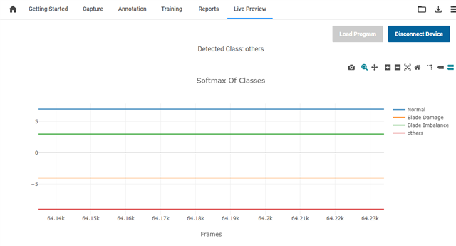
We are evaluating the system under the following environment; however, the results displayed on the Live Preview screen are not as expected.

Even though no modifications have been made to the motor, the classification result is shown as “Other” instead of “Normal.”

image.png

Could you please point out if there are any mistakes in our procedure?
Also, is this behavior already reported in the errata mentioned below?
:Edge AI Studio for Time Series - Quick Start Guide

■ Evaluation Environment

  • Hardware: LP-MSPM0G5187
  • Motor: SUNON EF80251S1-1000U-A99 (powered either by an external 12 V supply or by 5 V from the EVM)
  • Sensor: ADXL355
  • CCS: v20.5.1
  • M0 SDK: v2.10.00.04
  • Sample project: motor_fault_live_preview_LP_MSPM0G5187_nortos_ticlang
  • Compiler: 4.00.04.00
  • Edge AI Studio for Time Series: v1.6.1
  • AI sample project: Fan Imbalance Classification

■ Observation

The result does not change regardless of which of the following methods is used:

Pattern 1:
Build motor_fault_live_preview_LP_MSPM0G5187_nortos_ticlang in CCS and flash the generated .out file

Pattern 2:
Train the model based on Fan Imbalance Classification with default settings, and then program the device using “Load Program”

In addition, we captured our own data using motor_fault_data_capture_LP_MSPM0G5187_nortos_ticlang, and the data appears consistent with the default “Normal” dataset.
When the fan blades are touched with a finger, “Imbalance” is detected, which confirms that the sensor is operating properly.
The result remains the same even when using a different PC.
We also tested several different types of motors. 

■ Additional Findings (from comparison using F28P550)

The following issues were identified during comparative investigation with F28P550:

Best regards,
O.H

  • Hi O.H,

    I will do some test after I back office next Tuesday.

    B.R.

    Sal

  • Hi O.H.

    The result does not change regardless of which of the following methods is used:

    According to your capture behavior, looks like the sensor and capture demo works. But the live preview demo does not work.

    Unfortunately, I have no hardware in my side to test it; I will forward to internal team to see if it is a known issue.

    The following issues were identified during comparative investigation with F28P550:

    Thanks for sharing the findings for C2000 device. While I see you mentioned the data capture demo works, I think there should have no issues on the hardware connection.

    B.R.

    Sal

  • Additionally, when you run the demo, could you please help check the data from ADXL355 to M0 launchpad to see whether the live preview demo has corrected hardware setting?

    B.R.

    Sal

  • Hi Sal,

    Sorry for late reply. Thnak your for you supports.

    Additionally, when you run the demo, could you please help check the data from ADXL355 to M0 launchpad to see whether the live preview demo has corrected hardware setting?

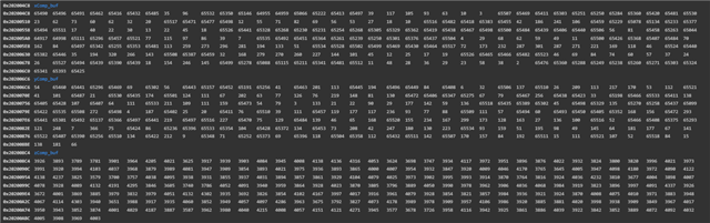
    The sensor is communicating, and the values ​​for all axes seem to be changing in the direction of tilt. However, as shown in the diagram below, the values ​​when the device is placed on a flat surface seem incorrect.

    Best regards,
    O.H

  • Hi Sal,

    First, I apologize that the measurement results are difficult to read.
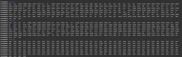
    I added buffers to “motor_fault_data_capture_LP_MSPM0G5187_nortos_ticlang” and visualized the measured values for the X, Y, and Z axes.
    The sensor was mounted on top of the fan, and measurements were taken under the following three patterns. 
    As a result, the sensor itself appears to be operating, but I cannot determine whether the measured values are valid or reasonable. When the sensor is not mounted on the fan, each axis shows changes in the expected direction according to the direction in which the sensor is tilted.

    Pattern 1: Normal condition. The values are stable on all axes.

    Pattern 2: Touching the blade with a finger. The values fluctuate significantly on all axes.

    Pattern 3: Attaching tape to the blade. The values fluctuate on all axes, but not as much as in Pattern 2.

    Best regards,
    O.H

  • Hi Sal,

    Sorry for rush you, is there any update?

    Best regards,
    O.H

  • Hi O.H.

    I have forwarded to thread to the experts within my team, I am also waiting the comments. Let me send another message to the team.

    B.R.

    Sal

  • Hi O.H.

    Please see the team feedback below:

    In our setup, the sensor is mounted on top of the BLDC motor and not on the blade for all 4 classes. This is different from what you are doing. Additionally, when you test the normal case, does the motor is spinning or keep static?

    For the demo set up if you put the sensor on the blade, then you need using capture demo to get enough data base for all classes and then re-train the model to deploy and test it in MCU side.

    B.R.

    Sal

  • Hi Sal,

    Thank you for your reply. Sorry for the insufficient explanation.

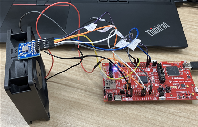
    In our setup, the sensor is mounted on top of the BLDC motor and not on the blade for all 4 classes. This is different from what you are doing.

    The setup is as shown in the photo. The sensor is mounted above the BLDC.

    Additionally, when you test the normal case, does the motor is spinning or keep static?

    The BLDC used is “SUNON EF80251S1-1000U-A99,” and it is always spinning.
    Since we only have one “SUNON EF80251S1-1000U-A99,” we have not damaged any of its blades. For another type of BLDC, we prepared both a normal unit and a unit with a damaged blade, and we have already tried the full process from custom data capture to re-train and compilation using “motor_fault_data_capture_LP_MSPM0G5187_nortos_ticlang.”

    For the demo set up if you put the sensor on the blade, then you need using capture demo to get enough data base for all classes and then re-train the model to deploy and test it in MCU side.

    Using “SUNON EF80251S1-1000U-A99,” we captured data with “motor_fault_data_capture_LP_MSPM0G5187_nortos_ticlang,” and we have confirmed the annotation, re-train, and compilation processes. As a result, “Normal” not appears at the top. Since there is a possibility that the annotation or training parameters may be incorrect, we tried to start by checking the operation with the sample project. This is the background.

    Best regards,
    O.H

  • Hi O.H.

    and we have confirmed the annotation, re-train, and compilation processes

    Have you compared the data when you do annotation and when you do live preview? I think if the re-train works, then you should get correct live preview in normal class.

    Could you share your re-trained model output (confusion matrix), and the data you captured and annotated for the normal/other class:

    B.R.

    Sal

  • Hi Sal,

    I've attached a project using the sample project as the default, and then another project based on that default using data I captured myself as the custom.

    The following graph summarizes the differences between the default and custom .csv files.

    Best regards,
    O.H

    Fan Imbalance Cllasification_default_project.zipFan Imbalance Cllasification_custom_project.zip20260521-143813_MotorFault_model_2_t_custom.zip20260520-175758_MotorFault_model_2_t_default.zip

  • Hi Sal,

    Sorry for rush you, is there any update? Please let us know if you need more information.

    Best regards,
    O.H

  • Hi Sal,

    Sorry for rush you, is there any update? Please let us know if you need more information.

    Best regards,
    O.H