MSPM0G3519-Q1: concurrent h/w averaging on both ADCs issue

Part Number: MSPM0G3519-Q1
Other Parts Discussed in Thread: SYSCONFIG

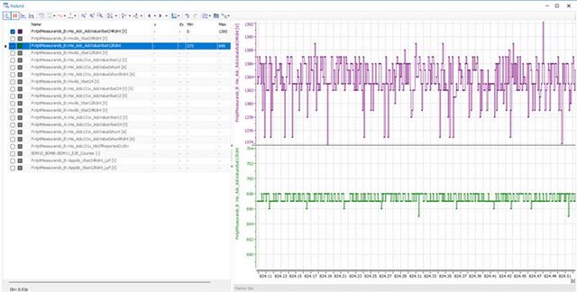
when h/w averaging is enabled on both ADCs concurrently, the output seems having averaging only on ADC0 but not on ADC1, if the only difference in the code that ADC0's h/w averaging is off - but setup for ADC1 is preserved - h/w averaging on ADC1 seems to be appearing. Unable to locate any info on such an issue. please advise.

  • this pic shows both ADCs with h/w averaging enabled

    this one shows purple channel having h/w averaging disabled while the green one has ZERO alterations :


  • Hi,

    Can you share you SysConfig file for reference?

    I suggest you can test the ADC conversion time for the channels, there can be observed with larger time after enable hardware averaging mode.

    B.R.

    Sal

  • Hey Sal, thanks for the reply, unfortunately my project doesn't use SysConfig

  • Hi,

    I have tested the function, and no obvious failure is captured. The hardware average function works fine for ADC0 and ADC1.

    Below is the test result:

    Below is the test code:

    #include "ti_msp_dl_config.h"
    
    volatile bool gCheckADC;
    volatile uint16_t gAdcResult0[200]={0};
    volatile uint16_t gAdcResult1[200]={0};
    volatile uint16_t cnt;
    
    int main(void)
    {
        SYSCFG_DL_init();
    
        cnt = 0;
    
        while (1) {
            DL_GPIO_clearPins(GPIO_LEDS_PORT, GPIO_LEDS_USER_LED_0_PIN);
            DL_ADC12_startConversion(ADC12_0_INST);
            while(DL_ADC12_getRawInterruptStatus(ADC12_0_INST, DL_ADC12_INTERRUPT_MEM0_RESULT_LOADED) != DL_ADC12_INTERRUPT_MEM0_RESULT_LOADED)
                ;
            gAdcResult0[cnt] = DL_ADC12_getMemResult(ADC12_0_INST, DL_ADC12_MEM_IDX_0);
            DL_GPIO_setPins(GPIO_LEDS_PORT, GPIO_LEDS_USER_LED_0_PIN);
            DL_ADC12_clearInterruptStatus(ADC12_0_INST, DL_ADC12_INTERRUPT_MEM0_RESULT_LOADED);
    
            delay_cycles(32);
    
            DL_GPIO_clearPins(GPIO_LEDS_PORT, GPIO_LEDS_USER_LED_1_PIN);
            DL_ADC12_startConversion(ADC12_1_INST);
            while(DL_ADC12_getRawInterruptStatus(ADC12_1_INST, DL_ADC12_INTERRUPT_MEM0_RESULT_LOADED) != DL_ADC12_INTERRUPT_MEM0_RESULT_LOADED)
                ;
            gAdcResult1[cnt] = DL_ADC12_getMemResult(ADC12_1_INST, DL_ADC12_MEM_IDX_0);
            DL_GPIO_setPins(GPIO_LEDS_PORT, GPIO_LEDS_USER_LED_1_PIN);
            DL_ADC12_clearInterruptStatus(ADC12_1_INST, DL_ADC12_INTERRUPT_MEM0_RESULT_LOADED);
    
            delay_cycles(32);
            cnt++;
            if(cnt==200)cnt=0;
            DL_ADC12_enableConversions(ADC12_0_INST);
            DL_ADC12_enableConversions(ADC12_1_INST);
        }
    }

    #include "ti_msp_dl_config.h"
    
    /*
     *  ======== SYSCFG_DL_init ========
     *  Perform any initialization needed before using any board APIs
     */
    SYSCONFIG_WEAK void SYSCFG_DL_init(void)
    {
        SYSCFG_DL_initPower();
        SYSCFG_DL_GPIO_init();
        /* Module-Specific Initializations*/
        SYSCFG_DL_SYSCTL_init();
        SYSCFG_DL_ADC12_0_init();
        SYSCFG_DL_ADC12_1_init();
    }
    
    SYSCONFIG_WEAK void SYSCFG_DL_initPower(void)
    {
        DL_GPIO_reset(GPIOA);
        DL_GPIO_reset(GPIOB);
        DL_GPIO_reset(GPIOC);
        DL_ADC12_reset(ADC12_0_INST);
        DL_ADC12_reset(ADC12_1_INST);
    
        DL_GPIO_enablePower(GPIOA);
        DL_GPIO_enablePower(GPIOB);
        DL_GPIO_enablePower(GPIOC);
        DL_ADC12_enablePower(ADC12_0_INST);
        DL_ADC12_enablePower(ADC12_1_INST);
        delay_cycles(POWER_STARTUP_DELAY);
    }
    
    SYSCONFIG_WEAK void SYSCFG_DL_GPIO_init(void)
    {
    
        DL_GPIO_initDigitalOutput(GPIO_LEDS_USER_LED_0_IOMUX);
    
        DL_GPIO_initDigitalOutput(GPIO_LEDS_USER_LED_1_IOMUX);
    
        DL_GPIO_clearPins(GPIO_LEDS_PORT, GPIO_LEDS_USER_LED_1_PIN);
        DL_GPIO_setPins(GPIO_LEDS_PORT, GPIO_LEDS_USER_LED_0_PIN);
        DL_GPIO_enableOutput(GPIO_LEDS_PORT, GPIO_LEDS_USER_LED_0_PIN |
    		GPIO_LEDS_USER_LED_1_PIN);
    
    }


    SYSCONFIG_WEAK void SYSCFG_DL_SYSCTL_init(void)
    {
    
    	//Low Power Mode is configured to be SLEEP0
        DL_SYSCTL_setBORThreshold(DL_SYSCTL_BOR_THRESHOLD_LEVEL_0);
    
        
    	DL_SYSCTL_setSYSOSCFreq(DL_SYSCTL_SYSOSC_FREQ_BASE);
    	/* Set default configuration */
    	DL_SYSCTL_disableHFXT();
    	DL_SYSCTL_disableSYSPLL();
    
    }
    
    
    /* ADC12_0 Initialization */
    static const DL_ADC12_ClockConfig gADC12_0ClockConfig = {
        .clockSel       = DL_ADC12_CLOCK_ULPCLK,
        .divideRatio    = DL_ADC12_CLOCK_DIVIDE_1,
        .freqRange      = DL_ADC12_CLOCK_FREQ_RANGE_24_TO_32,
    };
    SYSCONFIG_WEAK void SYSCFG_DL_ADC12_0_init(void)
    {
        DL_ADC12_setClockConfig(ADC12_0_INST, (DL_ADC12_ClockConfig *) &gADC12_0ClockConfig);
        DL_ADC12_configConversionMem(ADC12_0_INST, ADC12_0_ADCMEM_0,
            DL_ADC12_INPUT_CHAN_0, DL_ADC12_REFERENCE_VOLTAGE_VDDA_VSSA, DL_ADC12_SAMPLE_TIMER_SOURCE_SCOMP0, DL_ADC12_AVERAGING_MODE_ENABLED,
            DL_ADC12_BURN_OUT_SOURCE_DISABLED, DL_ADC12_TRIGGER_MODE_AUTO_NEXT, DL_ADC12_WINDOWS_COMP_MODE_DISABLED);
        DL_ADC12_setPowerDownMode(ADC12_0_INST,DL_ADC12_POWER_DOWN_MODE_MANUAL);
        DL_ADC12_configHwAverage(ADC12_0_INST,DL_ADC12_HW_AVG_NUM_ACC_32,DL_ADC12_HW_AVG_DEN_DIV_BY_32);
        DL_ADC12_setSampleTime0(ADC12_0_INST,16);
        DL_ADC12_enableConversions(ADC12_0_INST);
    }
    /* ADC12_1 Initialization */
    static const DL_ADC12_ClockConfig gADC12_1ClockConfig = {
        .clockSel       = DL_ADC12_CLOCK_ULPCLK,
        .divideRatio    = DL_ADC12_CLOCK_DIVIDE_1,
        .freqRange      = DL_ADC12_CLOCK_FREQ_RANGE_24_TO_32,
    };
    SYSCONFIG_WEAK void SYSCFG_DL_ADC12_1_init(void)
    {
        DL_ADC12_setClockConfig(ADC12_1_INST, (DL_ADC12_ClockConfig *) &gADC12_1ClockConfig);
        DL_ADC12_configConversionMem(ADC12_1_INST, ADC12_1_ADCMEM_0,
            DL_ADC12_INPUT_CHAN_0, DL_ADC12_REFERENCE_VOLTAGE_VDDA_VSSA, DL_ADC12_SAMPLE_TIMER_SOURCE_SCOMP0, DL_ADC12_AVERAGING_MODE_ENABLED,
            DL_ADC12_BURN_OUT_SOURCE_DISABLED, DL_ADC12_TRIGGER_MODE_AUTO_NEXT, DL_ADC12_WINDOWS_COMP_MODE_DISABLED);
        DL_ADC12_setPowerDownMode(ADC12_1_INST,DL_ADC12_POWER_DOWN_MODE_MANUAL);
        DL_ADC12_configHwAverage(ADC12_1_INST,DL_ADC12_HW_AVG_NUM_ACC_32,DL_ADC12_HW_AVG_DEN_DIV_BY_32);
        DL_ADC12_setSampleTime0(ADC12_1_INST,16);
        DL_ADC12_enableConversions(ADC12_1_INST);
    }
    

    /*
     *  ============ ti_msp_dl_config.h =============
     *  Configured MSPM0 DriverLib module declarations
     *
     *  DO NOT EDIT - This file is generated for the MSPM0G351X
     *  by the SysConfig tool.
     */
    #ifndef ti_msp_dl_config_h
    #define ti_msp_dl_config_h
    
    #define CONFIG_MSPM0G351X
    #define CONFIG_MSPM0G3519
    
    #if defined(__ti_version__) || defined(__TI_COMPILER_VERSION__)
    #define SYSCONFIG_WEAK __attribute__((weak))
    #elif defined(__IAR_SYSTEMS_ICC__)
    #define SYSCONFIG_WEAK __weak
    #elif defined(__GNUC__)
    #define SYSCONFIG_WEAK __attribute__((weak))
    #endif
    
    #include <ti/devices/msp/msp.h>
    #include <ti/driverlib/driverlib.h>
    #include <ti/driverlib/m0p/dl_core.h>
    
    #ifdef __cplusplus
    extern "C" {
    #endif
    
    /*
     *  ======== SYSCFG_DL_init ========
     *  Perform all required MSP DL initialization
     *
     *  This function should be called once at a point before any use of
     *  MSP DL.
     */
    
    
    /* clang-format off */
    
    #define POWER_STARTUP_DELAY                                                (16)


    #define CPUCLK_FREQ                                                     32000000


    /* Defines for ADC12_0 */
    #define ADC12_0_INST                                                        ADC0
    #define ADC12_0_INST_IRQHandler                                  ADC0_IRQHandler
    #define ADC12_0_INST_INT_IRQN                                    (ADC0_INT_IRQn)
    #define ADC12_0_ADCMEM_0                                      DL_ADC12_MEM_IDX_0
    #define ADC12_0_ADCMEM_0_REF                DL_ADC12_REFERENCE_VOLTAGE_VDDA_VSSA
    #define GPIO_ADC12_0_C0_PORT                                               GPIOA
    #define GPIO_ADC12_0_C0_PIN                                       DL_GPIO_PIN_27
    #define GPIO_ADC12_0_IOMUX_C0                                    (IOMUX_PINCM60)
    #define GPIO_ADC12_0_IOMUX_C0_FUNC                (IOMUX_PINCM60_PF_UNCONNECTED)
    
    /* Defines for ADC12_1 */
    #define ADC12_1_INST                                                        ADC1
    #define ADC12_1_INST_IRQHandler                                  ADC1_IRQHandler
    #define ADC12_1_INST_INT_IRQN                                    (ADC1_INT_IRQn)
    #define ADC12_1_ADCMEM_0                                      DL_ADC12_MEM_IDX_0
    #define ADC12_1_ADCMEM_0_REF                DL_ADC12_REFERENCE_VOLTAGE_VDDA_VSSA
    #define GPIO_ADC12_1_C0_PORT                                               GPIOA
    #define GPIO_ADC12_1_C0_PIN                                       DL_GPIO_PIN_15
    #define GPIO_ADC12_1_IOMUX_C0                                    (IOMUX_PINCM37)
    #define GPIO_ADC12_1_IOMUX_C0_FUNC                (IOMUX_PINCM37_PF_UNCONNECTED)


    /* Port definition for Pin Group GPIO_LEDS */
    #define GPIO_LEDS_PORT                                                   (GPIOA)
    
    /* Defines for USER_LED_0: GPIOA.0 with pinCMx 1 on package pin 1 */
    #define GPIO_LEDS_USER_LED_0_PIN                                 (DL_GPIO_PIN_0)
    #define GPIO_LEDS_USER_LED_0_IOMUX                                (IOMUX_PINCM1)
    /* Defines for USER_LED_1: GPIOA.1 with pinCMx 2 on package pin 2 */
    #define GPIO_LEDS_USER_LED_1_PIN                                 (DL_GPIO_PIN_1)
    #define GPIO_LEDS_USER_LED_1_IOMUX                                (IOMUX_PINCM2)
    
    
    /* clang-format on */
    
    void SYSCFG_DL_init(void);
    void SYSCFG_DL_initPower(void);
    void SYSCFG_DL_GPIO_init(void);
    void SYSCFG_DL_SYSCTL_init(void);
    void SYSCFG_DL_ADC12_0_init(void);
    void SYSCFG_DL_ADC12_1_init(void);


    #ifdef __cplusplus
    }
    #endif
    
    #endif /* ti_msp_dl_config_h */

    B.R.

    Sal

  • Hello Sal, thanks for the input. it turns out the culprit is     DL_ADC12_setPowerDownMode(ADC12_0_INST,DL_ADC12_POWER_DOWN_MODE_MANUAL);

    if it is set - always on - ADC produces pretty consistent returns, but in default powerdown-when-not-converting - the results on the same stable input are dispersed more widely. does it a known feature?

  • Hi Mykhaylo,

    Yes, this is mentioned in TRM ADC chapter:

    We recommend using manual power down mode if there has no extreme power consumption requirement.

    Otherwise, we need set larger sample time to cover the ADC wake up and enable time.

    B.R.

    Sal

  • Thank you Sal for helping me. What I was trying to get is the conversion results stability difference between always-on mode and default automatic powerdown. imagine the analog input of very stable 1V transits into digital 100 output of the ADC. if it is always-on - the readings are 99, 100 and 101, nothing more. but if automatic powerdown is in play - the readings start jump to 97,98, 102 and 103 at least with rare jumps to 96 or 104. could you see such effects on your side? does it documented anywhere? or maybe it is some issues with my board's layout and this is attributes of increased current drive where supply voltage dips and produces such readings? please advise

  • Hi Mykhaylo,

    As I mentioned, this is due to ADC is not stable to start ADC conversion when working in AUTO mode. We have no analysis on the relationship of its impact.

    While I believe if you set larger sample time (cover the ADC wakeup, enable, and original ADC channel sample time), then you can get the same stable ADC conversion result.

    The wake up time takes 5us max:

    The enable time normally takes several ULPCLK cycles:

    For example, if you set the original sample time as 1us, then you should set it to 1+5+0.1=6.1us to cover the required timing.

    This is insufficient way when work in hardware average mode, as only the first conversion requires the larger sample time to wait ADC wakeup, and the following repeat conversions (for hardware average) only seek for small sample time.

    B.R.

    Sal