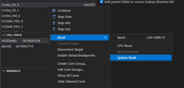
AM263P4: UniFlash reset

Part Number: AM263P4
Other Parts Discussed in Thread: UNIFLASH, LP-AM263P, SN74LVC1G07

I'm using the XDS110 JTAG debugger connected via a 10pin Cortex cable to our AM263P4 board.

When I use UniFlash (v 9.5.0.5651) I quite often find the board not being reset by the XDS110 and consequently the programming fails.

I can see this line in the console output on UniFlash but no reset happens. 

[INFO] Cortex_R5_0: GEL Output: CPU reset (soft reset) has been issued through GEL on program load.

Is there a way to get the XDS110 and/or UniFlash to provide a proper hardware reset using the RESET output ?

Regards

Neil

  • Hi Niel,

    It is not possible to do system reset via uniflash, it can only reset the CPU.

    Is there a way to get the XDS110 and/or UniFlash to provide a proper hardware reset using the RESET output ?

    While XDS110, you can do system reset 

  • Hi Nilabh,

    To follow up on this.

    What does the "cpu reset" or "system reset" actually do?

    Regards

    Neil

  • Thanks Nilabh,

    If I pull the WARM_RESET line low should I expect to see the MCU reset back to the boot loader ?

    Regards

    Neil 

  • Yes that is correct Neil

  • What is happening when UniFlash says:

    [INFO] Cortex_R5_0: GEL Output: CPU reset (soft reset) has been issued through GEL on program load

    I very often see no reset of the processor and UniFlash fails.

    Are there reasons why a "soft reset" would fail to reset the MCU?

    The only way I can program the board is to try and time a physical reset and click "Load Image"

    Regards

    Neil

  • Soft reset its just a core and register reset not mcu reset.

    The only way I can program the board is to try and time a physical reset and click "Load Image"

    Niel, Can you share your schematics with me over email.

  • Hi Nilabh, I have been using xds110reset and I see the warm reset line toggle on an oscilloscope.

    I do not see the MCU reset.

    In the AM263PX TRM it states:

    6.3.2.2.1 Warm Reset by WARMRSTn HW Pin

    This reset pin is the warm reset request (active LOW) given externally from the pad..

    By default, the input path to trigger a warm reset from external pad is disabled. To enable, the TOP_RCM.WARM_RESET_CONFIG.PAD_BYPASS bit should be written 3’b000.

    That means that warm reset is not enabled and I need to enable it in software?

    Is there an example anywhere on how to provide this enable?

    Regards

    Neil

  • Hi Neil,

    Yes you can find the same in SDK SBL example

    oid  SOC_generateSwWarmReset (void)
      Generate SW WARM reset. More...
  • Hi Nilabh, but this is the MCU creating the WarmReset ?

    What I want is to be able to use the warm reset input from an external source to reset the MCU.

    e.g. on the LP-AM263P dev board SW3 is connected via a resistor to the warm reset input to the MCU

    the user guide text suggests it resets the MCU.

    I do not see that action either on the LP or our own board.

    Is there some configuration needed to enable an input to the warm reset pin of the MCU to cause a reset.

  • By default, the input path to trigger a warm reset from external pad is disabled. To enable, the TOP_RCM.WARM_RESET_CONFIG.PAD_BYPASS bit should be written 3’b000.

    That means that warm reset is not enabled and I need to enable it in software?

    Is there an example anywhere on how to provide this enable?

    Regards

    Neil I understand now:

    The external warm reset input path is disabled by default. This is why pressing SW3 on the LP-AM263P or driving WARMRSTn low on your custom board has no effect. You must explicitly enable it via a register write.

    Required Configuration

    Write 3'b000 to the TOP_RCM.WARM_RESET_CONFIG.PAD_BYPASS field to enable the external pad as a warm reset source 1.

    Using the MCU+ SDK, this is done with:

    SOC_configureWarmResetSource(SOC_WarmResetSource_PAD_BYPASS);

    This call writes the appropriate mask (CSL_TOP_RCM_WARM_RESET_CONFIG_PAD_BYPASS_MASK) to enable the pad input 2.

    Why It Doesn't Work Out of the Box

    In its power-on-default state, the WARMRSTn pin is configured as an open-drain output (reset status indicator), not an input 3. It requires:

    • An external pull-up resistor to VDDS33 (3.3V)
    • The PAD_BYPASS register write to enable the input path

    No pin mux change is needed—WARMRSTn is a dedicated pin 4.

    Timing Considerations

    The external warm reset input path is disabled by default. This is why pressing SW3 on the LP-AM263P or driving WARMRSTn low on your custom board has no effect. You must explicitly enable it via a register write.

    Required Configuration
    Write 3'b000 to the TOP_RCM.WARM_RESET_CONFIG.PAD_BYPASS field to enable the external pad as a warm reset source 1.

    Using the MCU+ SDK, this is done with:


    SOC_configureWarmResetSource(SOC_WarmResetSource_PAD_BYPASS);
    This call writes the appropriate mask (CSL_TOP_RCM_WARM_RESET_CONFIG_PAD_BYPASS_MASK) to enable the pad input 2.

    Why It Doesn't Work Out of the Box
    In its power-on-default state, the WARMRSTn pin is configured as an open-drain output (reset status indicator), not an input 3. It requires:

    An external pull-up resistor to VDDS33 (3.3V)
    The PAD_BYPASS register write to enable the input path
    No pin mux change is needed—WARMRSTn is a dedicated pin 4.

    Timing Considerations
    Once enabled, the input signal must remain LOW for at least TOP_RCM.WARM_RSTTIME3 duration to register an assertion, and HIGH for at least TOP_RCM.WARM_RSTTIME2 to register deassertion. These are configurable via SDK functions:

    SOC_configureWarmResetInputFallDelay() — sets WARM_RSTTIME3
    SOC_configureWarmResetInputRiseDelay() — sets WARM_RSTTIME2
    Programmable values range from 500ns to 16.384ms 2.

    Board Design Note
    If you need both reset input (from a button/external source) and reset status output (to drive peripheral resets), use an open-drain buffer (e.g., SN74LVC1G07) to avoid bus contention, as done on the AM263x Control Card 3.

    Follow up: Are you calling SOC_configureWarmResetSource() early in your application initialization, and would you like guidance on verifying the reset cause via SOC_getWarmResetCause() after the MCU restarts?

    AM263Px Technical Reference Manual - Reset Chapter
    MCU+ SDK API Guide - RCM Module
    AM263Px Hardware Design Guide
    AM263Px Datasheet - Pin Attributes

    Once enabled, the input signal must remain LOW for at least TOP_RCM.WARM_RSTTIME3 duration to register an assertion, and HIGH for at least TOP_RCM.WARM_RSTTIME2 to register deassertion. These are configurable via SDK functions:

    • SOC_configureWarmResetInputFallDelay() — sets WARM_RSTTIME3
    • SOC_configureWarmResetInputRiseDelay() — sets WARM_RSTTIME2

    Programmable values range from 500ns to 16.384ms 2.


    1. AM263Px Technical Reference Manual - Reset Chapter
    2. MCU+ SDK API Guide - RCM Module
    3. AM263Px Hardware Design Guide
    4. AM263Px Datasheet - Pin Attributes
  • Thanks Nilabh,

    Are here any restrictions where this call is used?

    I am using the hello_world_am263px-lp_r5fss0-0_nortos_ti-arm-clang example.

    When I call SOC_configureWarmResetSource(SOC_WarmResetSource_PAD_BYPASS);

    The program traps in HwiP_user_data_abort_handler_c

    Regards

    Neil

  • Hi Neil, Let me look into it tomorrow.,

  • Hi Nilabh, have you managed to make any progress with this please? 

    Regards

    Neil