AM2631-Q1: AM263X - Warm RESET due to HSM_WDT

Part Number: AM2631-Q1
Other Parts Discussed in Thread: LP-XDS110, , SYSCONFIG, LP-AM263

Hello,

I have a AM2631-Q1 on a custom PCB that is resetting every 3 minutes (or 180 seconds) after applying power.  I'm able to program it and run the debugger using an LP-XDS110 with a custom made cable.  I narrowed down that it is a system reset that is occurring based off of page 195 in the technical review manual (TRM).  It is occurring repeatedly and rarely is it running normally without a system reset which interrupts the LP-XDS110 debugger.  After reading some more documentation in the TRM, I located the TOP_RCM_SYS_RST_CAUSE register and added it to the watch window.  I then cleared the TOP_RCM_SYS_RST_CAUSE_CLR by writing 0x3 in the TOP_RCM_SYS_RST_CAUSE_CLR register and watched TOP_RCM_SYS_RST_CAUSE register go back to 0x0 with power still applied.  After another 3 minutes when it reset, I re-ran the debugger and noticed the TOP_RCM_SYS_RST_CAUSE register updated with value 12'b0000_1100_0000 or 0x0C0 in hex which corresponds to a "Warm reset due to HSM_WDT" from the description of the TOP_RCM_SYS_RST_CAUSE register in CCS.  My question is, what could be causing this warm reset due to the HSM WDT?  I can't find any information about this WDT in the TRM besides identifying the register and figuring out the reset cause.

We have an identical board with identical software that is not showing this issue.  My CCS version is 20.5.0.28 and I am also using the MCU+ SDK for AM263X version 10.02.00.13.  We are just running our application code through the LP-XDS110 in RAM and not programming the external flash.  We have also tried different boot modes (e.g. DevBoot) and it's still exhibiting the same behavior.  We have also tried just applying power to the board without the LP-XDS110 connected and notice it is resetting every 3 minutes with no code running.  We do not have the HSMCLIENT or any TI HSM Services configured in the SYSCONFIG.

Thank you!

  • Hi 

    May I know if you are using the control card or Launch pad or custom board?

    HSM WDT reset would occur typically in QSPI boot mode when there is an error loading the SBL or HSMRT. 

    Could you please confirm again if this is occurring the Dev boot mode by checking the SOP pins?

    The HSM WDT reset should not occur in Dev Boot mode.

    Note: Please do a flash erase, so that there is no application/ BL present in the flash

    Thanks and Regards,

    Nikhil Dasan

  • Hello,

    Thank you for the explanation of the HSM WDT reset.  To answer your other questions:

    • This is a custom board
    • We confirmed that the SOP values are being driven correctly for DevBoot.  They are also being driven before POR de-asserts.
      • SOP0 measured 3.33V
      • SOP1 measured 3.33V
      • SOP2 measured 0.303V
      • SOP3 measured 3.33V

    Could it also be that our RC time constant for driving the SOP lines is not long enough in time?  I noticed that the LP-AM263 Launchpad board uses a 49.9 Ohm resistor and 10nF capacitor for a delay.  However, the note below it says that this creates a PORz RC delay of 1ms which is incorrect.  When we measure it, it was more along the lines of 1us (from AM263 PORZ net on R19 transitioning HIGH to SOP DRIVE OEN R net on U5A pin 4 transitioning HIGH).

    From the PROC111 Rev E2 schematic of the LP-AM263 Launchpad:

    Should we try increasing this GND to +3V RC time delay to 1ms?  The only thing I wouldn't understand though is, if that's the issue, how is the Launchpad working on such a short delay?

    Thank you!

  • Hi John,

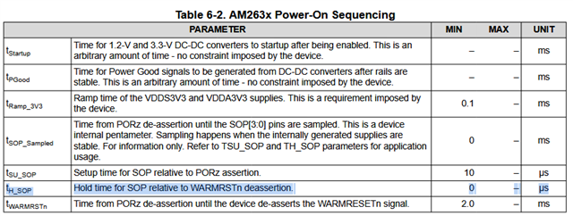
    I don't think the RC delay is an issue. As you mentioned the delay value mentioned in the schematics is wrong. The actual delay value is in the order of 1us as you have correctly mentioned. The hold time requirement from datasheet is actually 0µs, so it is not a problem even if we have very less hold time on this SOP lines.

    Were you able to try the flash erase as suggested by Nikhil?

    Thanks,
    Tejas Kulakarni

  • Hello,

    We found out a bit more information (detailed below) and we have found a workaround for now.  The workaround is that we are able to load in our SBL code to flash and drive all of the SOP pins LOW which puts it in QSPI Quad Read mode for boot.  The problem still exists when trying the DevBoot mode, but the workaround works well enough for us to continue on with our development and is resolved.

    I think the problem still has something to do with the SOP boot mode pins.  When using the LP-AM263 Launchpad, when we set switch 3 on the SW1 to ON (left position towards the high resistors on the LP-AM263 Launchpad), the boot mode pins are being driven correctly and we are reading 0xB (b1011) in the TOP_RCM_SOP_MODE_VALUE register which corresponds to DevBoot from Table 5-2 in the TRM.  When we try the same switch positions on our custom board, we are getting 0x3 in the TOP_RCM_SOP_MODE_VALUE register which doesn't correspond to any boot mode and is unsupported.  We have tried different RC time constants and even lengthened it to a max delay of about 1.75ms from the time the PORz is de-asserted until the SOP pins are switching from being driven to a Hi-Z output through our SOP tri-state buffer.  When measuring the length of time between the PORz de-assertion to the WARMRSTN de-assertion we are measuring about 3.5ms.  Therefore, we are still driving the SOP pins while in WARMRSTN, and are transitioning to Hi-Z output before WARMRSTN so that there is no bus contention with the QSPI bus.

    I think there still exists a problem somewhere where the SOP pins aren't being driven correctly to the AM2631-Q1, but the workaround is still satisfactory for now by using the QSPI - Quad Read boot mode.  Thanks again for the help and explanations.

  • Hello,

    Never mind we have found our issue and it's hardware based.  The output of the tri-state buffer for SOP3 pin was not being directly connected to the ball on C10 for DevBoot mode due to a netlist error.  We figured this out whenever we were switching switch 4 on and off and getting the same value for the TOP_RCM_SOP_MODE_VALUE register.  Thanks again for all of the explanations and helping us troubleshoot our issue.  Consider this problem resolved.

  • Hi John,

    Thank you so much for letting us know. Happy to know the issue is resolved!!

    Regards,
    Tejas Kulakarni