Part Number: MSPM33C321A
I am using the SPI to send a bit stream. I found that the Motorola SPI mode leaves gaps between the bytes. The TI Synchronoud mode does not, but it puts an extra bit into the first byte.
I made a slight modification to the "spi_controller_multibyte_fifo_poll_LP_MSPM33C321A_nortos_ticlang" example to show the problem.
#include "ti_msp_dl_config.h"


/*

 * Number of bytes for SPI packet size

 * The packet will be transmitted by the SPI controller.

 * This example uses FIFOs with polling, and the maximum FIFO size is 4.

 * Refer to interrupt examples to handle larger packets.

 */

#define SPI_PACKET_SIZE (2)


/* Data for SPI to transmit */

// packet size 4

//uint8_t gExpectedRxPacket[SPI_PACKET_SIZE] = {0x1, 0x2, 0x3, 0x4};

//uint8_t gTxPacket[SPI_PACKET_SIZE]         = {0xAA, 0x00, 0xFF, 0x55};


// packet size 2

uint8_t gExpectedRxPacket[SPI_PACKET_SIZE] = {0x1, 0x2};

uint8_t gTxPacket[SPI_PACKET_SIZE]         = {0xAA, 0x55};


volatile uint8_t gRxPacket[SPI_PACKET_SIZE];

#ifdef __SLATE_INTERNAL__

volatile bool gTransactionCompleted = false;

#endif

int main(void)

{

    SYSCFG_DL_init();


#ifdef __SLATE_INTERNAL__

    __BKPT(0);

#endif

    /* Fill TX FIFO with data and transmit to SPI Peripheral */

    DL_SPI_fillTXFIFO8(SPI_0_INST, &gTxPacket[0], SPI_PACKET_SIZE);


    /* Wait until all bytes have been transmitted and the TX FIFO is empty */

    while (DL_SPI_isBusy(SPI_0_INST))

        ;


    for (uint8_t i = 0; i < SPI_PACKET_SIZE; i++) {

        gRxPacket[i] = DL_SPI_receiveDataBlocking8(SPI_0_INST);

    }

#ifdef __SLATE_INTERNAL__

    gTransactionCompleted = true;

#endif

    /*

         * If this example is used with the spi_peripheral_multibyte_fifo_poll

         * example, the expected data to receive in gRxPacket is

         * {0x01, 0x02, 0x03, 0x04}.

         */


    /* If write and read were successful, toggle LED */


    while (!DL_SPI_isTXFIFOEmpty(SPI_0_INST))

        ;


    int allCorrect = 1;

    for (int i = 0; i < SPI_PACKET_SIZE; i++) {

        if (gExpectedRxPacket[i] != gRxPacket[i]) allCorrect = 0;

    }


    if (allCorrect == 1) {

        DL_GPIO_setPins(GPIO_LEDS_PORT, GPIO_LEDS_PASS_LED_PIN);

    }

    else{

        DL_GPIO_setPins(GPIO_LEDS_PORT, GPIO_LEDS_FAIL_LED_PIN);

    }

    __BKPT(0);

}
The only real difference is to change the data being sent and changing the SPI mode.
When using the example's Motorola 4 wire SPI mode, I get this:
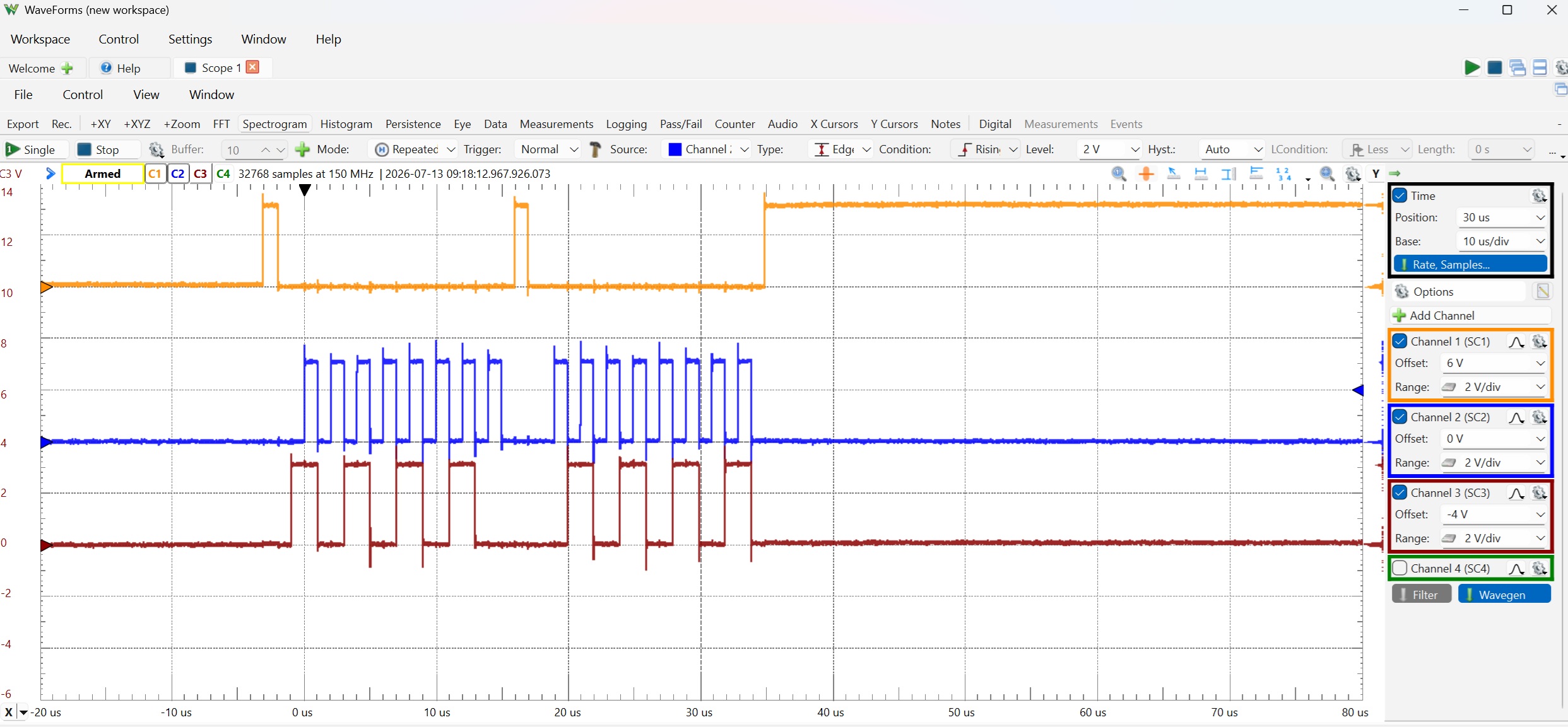
You can count that there is a gap between bytes and 16 clocks. When I switch to the TI Synchronous:
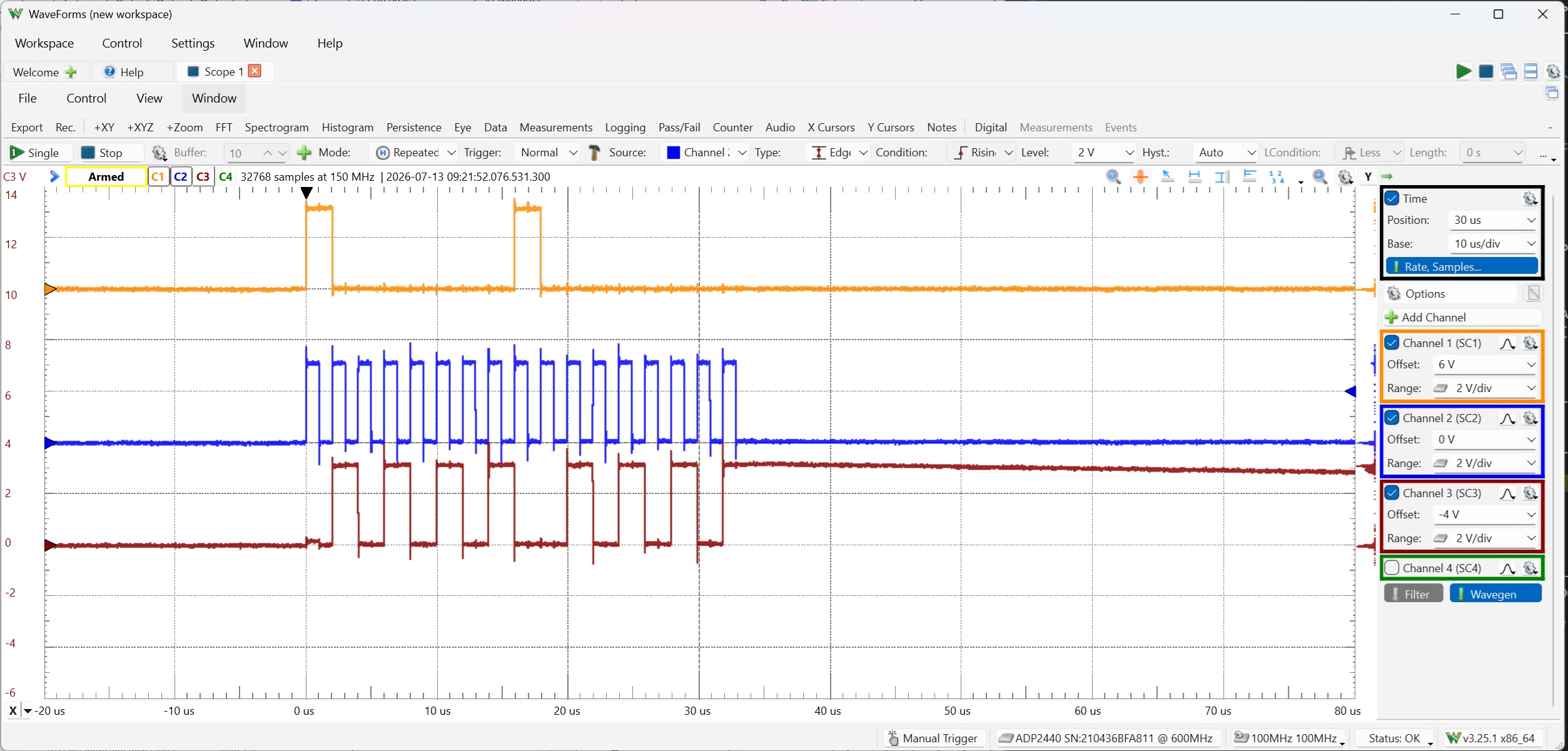
The gaps are gone, but now I get 17 clocks. On some of my tests, it actually stretches the first pulse so I get two ones in a row where there should be only one.
I did not see any errata that pertained to this. Am I doing something wrong?