Part Number: MSPM33C321A
Other Parts Discussed in Thread: SYSCONFIG
I have a program that sends a serial stream using spi, DMA and a timer to send a 400 us frame every 400us. I thought I would try to get a Ping-Pong setup going to try it out. (The clock is 5 MB/sec, so the single frame is 250 bytes long.)
I think I have it set up correctly, but the DL_SPI_IIDX_DMA_DONE_TX: interrupt fires every 30 us instead of 800 us as I would expect.
The DMA config is not very interesting, so I won't show it here.
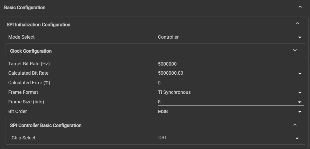
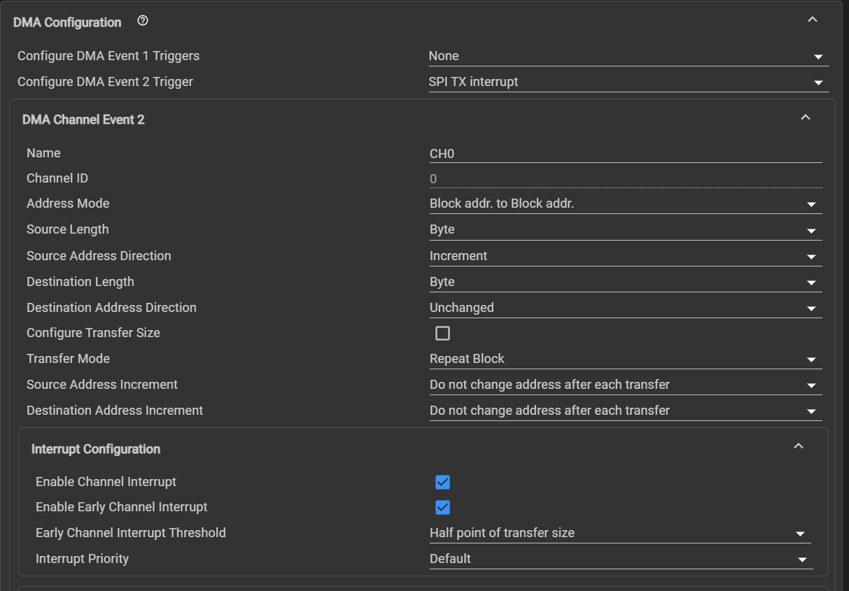
The SPI config is:

volatile bool DoTop, DoBottom;

uint8_t FrameData[] = {
    // Frame #1 "The Top"
    // 0    1     2     3     4     5     6     7     8    10     11    12    13
    // 14    15    16
    0xFE, 0x6B, 0x28, 0x40, 0x00, 0x05, 0x06, 0x07, 0x08, 0x09, 0x0A, 0x0B,
    0x0C, 0x0D, 0x0E, 0x0F, 0x10, 0x11, 0x12, 0x13, 0x14, 0x15, 0x16, 0x17,
    0x18, 0x19, 0x1A, 0x1B, 0x1C, 0x1D, 0x1E, 0x1F, 0x20, 0x21, 0x22, 0x23,
    0x24, 0x25, 0x26, 0x27, 0x28, 0x29, 0x2A, 0x2B, 0x2C, 0x2D, 0x2E, 0x2F,
    0x30, 0x31, 0x32, 0x33, 0x34, 0x35, 0x36, 0x37, 0x38, 0x39, 0x3A, 0x3B,
    0x3C, 0x3D, 0x3E, 0x3F, 0x40, 0x41, 0x42, 0x43, 0x44, 0x45, 0x46, 0x47,
    0x48, 0x49, 0x4A, 0x4B, 0x4C, 0x4D, 0x4E, 0x4F, 0x50, 0x51, 0x52, 0x53,
    0x54, 0x55, 0x56, 0x57, 0x58, 0x59, 0x5A, 0x5B, 0x5C, 0x5D, 0x5E, 0x5F,
    0x60, 0x61, 0x62, 0x63, 0x64, 0x65, 0x66, 0x67, 0x68, 0x69, 0x6A, 0x6B,
    0x6C, 0x6D, 0x6E, 0x6F, 0x70, 0x71, 0x72, 0x73, 0x74, 0x75, 0x76, 0x77,
    0x78, 0x79, 0x7A, 0x7B, 0x7C, 0x7D, 0x7E, 0x7F, 0x80, 0x81, 0x82, 0x83,
    0x84, 0x85, 0x86, 0x87, 0x88, 0x89, 0x8A, 0x8B, 0x8C, 0x8D, 0x8E, 0x8F,
    0x90, 0x91, 0x92, 0x93, 0x94, 0x95, 0x96, 0x97, 0x98, 0x99, 0x9A, 0x9B,
    0x9C, 0x9D, 0x9E, 0x9F, 0xA0, 0xA1, 0xA2, 0xA3, 0xA4, 0xA5, 0xA6, 0xA7,
    0xA8, 0xA9, 0xAA, 0xAB, 0xAC, 0xAD, 0xAE, 0xAF, 0xB0, 0xB1, 0xB2, 0xB3,
    0xB4, 0xB5, 0xB6, 0xB7, 0xB8, 0xB9, 0xBA, 0xBB, 0xBC, 0xBD, 0xBE, 0xBF,
    0xC0, 0xC1, 0xC2, 0xC3, 0xC4, 0xC5, 0xC6, 0xC7, 0xC8, 0xC9, 0xCA, 0xCB,
    0xCC, 0xCD, 0xCE, 0xCF, 0xD0, 0xD1, 0xD2, 0xD3, 0xD4, 0xD5, 0xD6, 0xD7,
    0xD8, 0xD9, 0xDA, 0xDB, 0xDC, 0xDD, 0xDE, 0xDF, 0xE0, 0xE1, 0xE2, 0xE3,
    0xE4, 0xE5, 0xE6, 0xE7, 0xE8, 0xE9, 0xEA, 0xEB, 0xEC, 0xED, 0xEE, 0xEF,
    0xF0, 0xF1, 0xF2, 0xF3, 0xF4, 0xF5, 0xF6, 0xF7, 0xF8, 0xF9,

    // Frame # 2 "The Bottom"
    // 0    1     2     3     4     5     6     7     8    10     11    12    13
    // 14    15    16
    0xFE, 0x6B, 0x28, 0x40, 0x01, 0x05, 0x06, 0x07, 0x08, 0x09, 0x0A, 0x0B,
    0x0C, 0x0D, 0x0E, 0x0F, 0x10, 0x11, 0x12, 0x13, 0x14, 0x15, 0x16, 0x17,
    0x18, 0x19, 0x1A, 0x1B, 0x1C, 0x1D, 0x1E, 0x1F, 0x20, 0x21, 0x22, 0x23,
    0x24, 0x25, 0x26, 0x27, 0x28, 0x29, 0x2A, 0x2B, 0x2C, 0x2D, 0x2E, 0x2F,
    0x30, 0x31, 0x32, 0x33, 0x34, 0x35, 0x36, 0x37, 0x38, 0x39, 0x3A, 0x3B,
    0x3C, 0x3D, 0x3E, 0x3F, 0x40, 0x41, 0x42, 0x43, 0x44, 0x45, 0x46, 0x47,
    0x48, 0x49, 0x4A, 0x4B, 0x4C, 0x4D, 0x4E, 0x4F, 0x50, 0x51, 0x52, 0x53,
    0x54, 0x55, 0x56, 0x57, 0x58, 0x59, 0x5A, 0x5B, 0x5C, 0x5D, 0x5E, 0x5F,
    0x60, 0x61, 0x62, 0x63, 0x64, 0x65, 0x66, 0x67, 0x68, 0x69, 0x6A, 0x6B,
    0x6C, 0x6D, 0x6E, 0x6F, 0x70, 0x71, 0x72, 0x73, 0x74, 0x75, 0x76, 0x77,
    0x78, 0x79, 0x7A, 0x7B, 0x7C, 0x7D, 0x7E, 0x7F, 0x80, 0x81, 0x82, 0x83,
    0x84, 0x85, 0x86, 0x87, 0x88, 0x89, 0x8A, 0x8B, 0x8C, 0x8D, 0x8E, 0x8F,
    0x90, 0x91, 0x92, 0x93, 0x94, 0x95, 0x96, 0x97, 0x98, 0x99, 0x9A, 0x9B,
    0x9C, 0x9D, 0x9E, 0x9F, 0xA0, 0xA1, 0xA2, 0xA3, 0xA4, 0xA5, 0xA6, 0xA7,
    0xA8, 0xA9, 0xAA, 0xAB, 0xAC, 0xAD, 0xAE, 0xAF, 0xB0, 0xB1, 0xB2, 0xB3,
    0xB4, 0xB5, 0xB6, 0xB7, 0xB8, 0xB9, 0xBA, 0xBB, 0xBC, 0xBD, 0xBE, 0xBF,
    0xC0, 0xC1, 0xC2, 0xC3, 0xC4, 0xC5, 0xC6, 0xC7, 0xC8, 0xC9, 0xCA, 0xCB,
    0xCC, 0xCD, 0xCE, 0xCF, 0xD0, 0xD1, 0xD2, 0xD3, 0xD4, 0xD5, 0xD6, 0xD7,
    0xD8, 0xD9, 0xDA, 0xDB, 0xDC, 0xDD, 0xDE, 0xDF, 0xE0, 0xE1, 0xE2, 0xE3,
    0xE4, 0xE5, 0xE6, 0xE7, 0xE8, 0xE9, 0xEA, 0xEB, 0xEC, 0xED, 0xEE, 0xEF,
    0xF0, 0xF1, 0xF2, 0xF3, 0xF4, 0xF5, 0xF6, 0xF7, 0xF8, 0xF9};

uint8_t *TopFrame = &FrameData[0];
uint8_t *BotFrame = &FrameData[250];
#define FRAME_PACKET_SIZE (250)

#define FRAME_BUFFER_SIZE (sizeof(FrameData) / sizeof(FrameData[0]))

uint32_t NumFrame = 1;

int main(void) {
  DoTop = false;
  DoBottom = false;
  int crc16;

  SYSCFG_DL_init();
  DL_SYSCTL_disableSleepOnExit();

  /*
   * Configure DMA0 source, destination and size to transfer data from
   * gTxPacket to TXDATA. The DMA0 transfer will start when TX interrupt is
   * set, which it should already be set (which indicates that the SPI is
   * ready to transfer) so the DMA0 will begin this transfer when the channel
   * is enabled.
   */
  DL_SPI_disableDMATransmitEvent(SPI_0_INST);

  DL_DMA_setSrcAddr(DMA0, DMA0_CH0_CHAN_ID, (uint32_t)&FrameData[0]);
  DL_DMA_setDestAddr(DMA0, DMA0_CH0_CHAN_ID,
                     (uint32_t)(&SPI_0_INST->spi->TXDATA));

  DL_DMA_setTransferSize(DMA0, DMA0_CH0_CHAN_ID, FRAME_BUFFER_SIZE);

  NVIC_EnableIRQ(SPI_0_INST_INT_IRQN);

  DL_SPI_enableInterrupt(SPI_0_INST, (DL_SPI_INTERRUPT_DMA_PREIRQ_TX |
                                      DL_SPI_INTERRUPT_DMA_DONE_TX |
                                      DL_SPI_INTERRUPT_TX_EMPTY));

  DL_DMA_enableChannel(DMA0, DMA0_CH0_CHAN_ID);
  DL_SPI_enableDMATransmitEvent(SPI_0_INST);


  while (1) {
    // Watch the interrupts
    // when the interrupt is at 1/2 fill the top frame
    // when the interrupt says the Xfer is done, fill the bottom half
    if (DoTop == true) {
      // Fill the top
      DL_GPIO_setPins(GPIO_DEBUG_PORT, GPIO_DEBUG_PC10_PIN);

      // Frame number: word 222, 223, 224, 225: 225 is LSB

      TopFrame[221] = (uint8_t)(0xFF & (NumFrame >> 24));
      TopFrame[222] = (uint8_t)(0xFF & (NumFrame >> 16));
      TopFrame[223] = (uint8_t)(0xFF & (NumFrame >> 8));
      TopFrame[224] = (uint8_t)(0xFF & NumFrame);

      NumFrame++;

      SYSCFG_DL_CRCP_init();

      for (int i = 0; i < (FRAME_PACKET_SIZE-2); i++) { // '-2' since no reason to CRC the CRC bytes!
        DL_CRCP_feedData8(CRCP0, TopFrame[i]);
      }
      crc16 = DL_CRCP_getResult16(CRCP0);


      TopFrame[248] = (uint8_t)(0xFF & (crc16 >> 8));
      TopFrame[249] = (uint8_t)(0xFF & (crc16));

      DL_GPIO_clearPins(GPIO_DEBUG_PORT, GPIO_DEBUG_PC10_PIN);

      DoTop = false;

    }

    if (DoBottom == true) {
      //Fill The bottom
       DL_GPIO_setPins(GPIO_DEBUG_PORT, GPIO_DEBUG_PC11_PIN);
      // We have actually finished the frame

      // Frame number: word 222, 223, 224, 225: 225 is LSB

      BotFrame[221] = (uint8_t)(0xFF & (NumFrame >> 24));
      BotFrame[222] = (uint8_t)(0xFF & (NumFrame >> 16));
      BotFrame[223] = (uint8_t)(0xFF & (NumFrame >> 8));
      BotFrame[224] = (uint8_t)(0xFF & NumFrame);

      NumFrame++;

      SYSCFG_DL_CRCP_init();

      for (int i = 0; i < (FRAME_PACKET_SIZE-2); i++) { // '-2' since no reason to CRC the CRC bytes!
        DL_CRCP_feedData8(CRCP0, BotFrame[i]);
      }
      crc16 = DL_CRCP_getResult16(CRCP0);


      BotFrame[248] = (uint8_t)(0xFF & (crc16 >> 8));
      BotFrame[249] = (uint8_t)(0xFF & (crc16));

      DL_GPIO_clearPins(GPIO_DEBUG_PORT, GPIO_DEBUG_PC11_PIN);

      DoBottom = false;

    }

    // do whatever else
  }
}

void SPI_0_INST_IRQHandler(void) {
  switch (DL_SPI_getPendingInterrupt(SPI_0_INST)) {
  case DL_SPI_IIDX_DMA_DONE_TX:
    /* DMA0 is done transferring the bottom half, start filling it */
    DoBottom = true;
    DL_GPIO_setPins(GPIO_DEBUG_PORT, GPIO_DEBUG_PC12_PIN);
    DL_GPIO_clearPins(GPIO_DEBUG_PORT, GPIO_DEBUG_PC12_PIN);
  case DL_SPI_IIDX_PREIRQ_TX:
    /* DMA0 is done transferring the top half, start filling it */
    DoTop = true;
    break;

  default:
    break;
  }
}
Is there some setting I am missing?