


Part Number: AM2434
Hello,
I would like to use the ADC on the AM2434 to measure the current of a motor phase. I have designed the following circuit for this purpose:
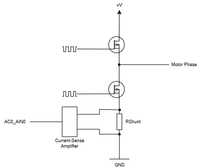
As shown in the (simplified) circuit diagramm, the shunt resistor is not located directly in the motor phase path, but is placed in one of the two gate paths, with the gates receiving a square-wave signal from the EPWM and, in the case of the lower gate, the inverted square-wave signal. Thus, the design already defines that current measurement is only possible when the corresponding gate is activated.
To ensure that the current measurement takes place reliably at a specific point in the time within the EPWM period, it is necessary to use a hardware trigger for the ADC as well as to use continous mode. Since I am already using the IEP for similar purposes, the event ICSS-G0 IEP0 CMP15 (described in Section 12.1.1.3.1 of the TRM) was the ideal choice for me.
However, I'm having trouble measuring the motor phase current correctly - more specifically, the measured current is lower than expected depending on the duty cycle. For example, at a duty cycle of 50%, the measured current is half the expected value. Before I go into more detail, I'd like to note that I've verified the basic conversion forular in the software. To do this, I applied a constant current to the shunt resistor on the PCB. The calculated current in the AM2434 software an the current set on the lab power supply matched in a small measuring series (except for minimal variations around the LSB)
To investigate the issue further, I configured a debug pin that is toggled every time the ADC callback for the specific ADC step is called. You can see two oscilloscope waveforms below. Red shows the EPWM signal, and blue the GPIO signal. These should show that the measurement time (triggered by the IEP CMP15) was configured one time during the EPWM's HIGH phase and one time during its LOW phase (although slight inaccuracies arise due to the method of the measurement, these are negligible).
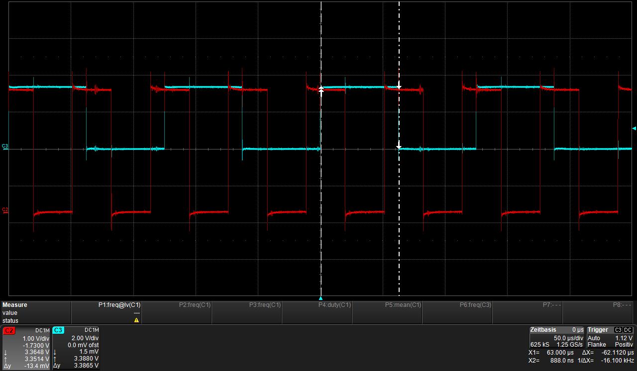
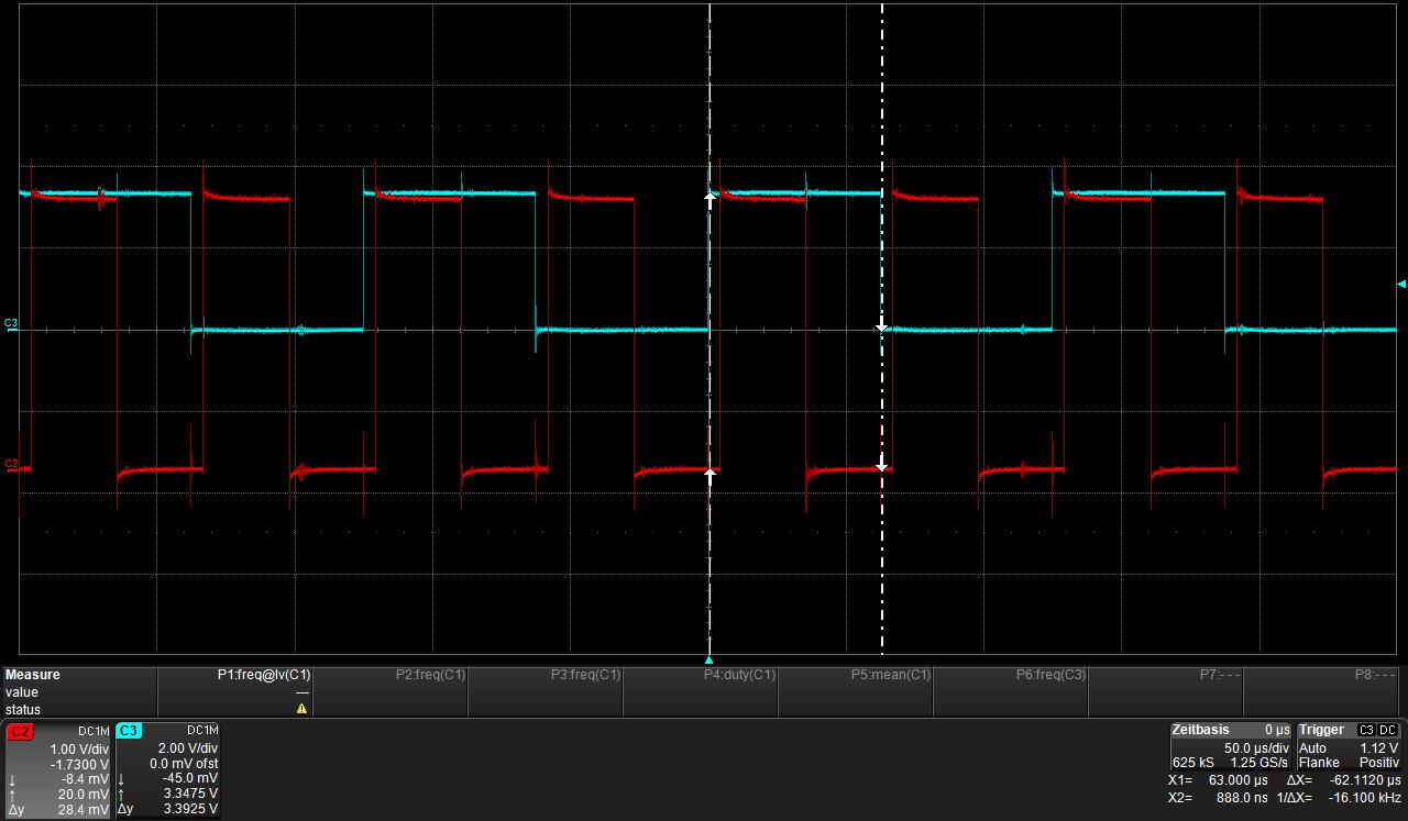
As I mentioned earlier, I'm measuring an incorrect signal. Although the ADC is measuring the sine wave of the motor phase, it is approximately a factor of 2 smaller. What's causing this? Is the circuit design incorrectly? Or is the ADC configured incorrectly. Here are all the settings:
| Channel | ADC_AIN2 |
| Step | 3 |
| Mode | HW synchronized, continous |
| Open Delay | 0 |
| Sample Delay | 0 |
| Range Check | false |
| Averaging | none |
| FIFO | FIFO1 |
Furthermore, the ADC is configured to only use 'End of Sequence' as interrupt source.
I'd appreciate some help on this topic.
Best regards,
Christian