This thread has been locked.

If you have a related question, please click the "Ask a related question" button in the top right corner. The newly created question will be automatically linked to this question.

InstaSPIN Control for the TMS570LS12x

Other Parts Discussed in Thread: TMS570LS1227

Hi,

I got DRV8301-EVM kit. And now I am trying to work BLDC motor that it is included in EVM kit.

I built sample project that is in /sw/solutions/instaspin_bldc/boards/drv8301kit_revD/tms570ls1227/projects/ccs5/porject01. And I tried to run it.

But I got some error after execution script. Please see below.

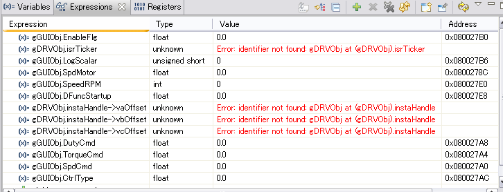
gDRVObj.isrTicker is Error.

gDRVObj.instaHandle -> vaOffset is Error.

gDRVObj.instaHandle -> vbOffset is Error.

gDRVObj.instaHandle -> vcOffset is Error.

I don't know the cause of the above errors.

Please advise me how to solve this problem.

Best regards,

Michi

  • They show as an error because the CCS compiler optimize them (I don't think they are not used in the now running flow).

    You can choose to ignore them, or remove them from the watch window.

    Or if you really want to see it, disable the optimization of the project or set to a lower level of optimation, and these variables should be able to show up.

    Regards,

    Haixiao

  • Dear Haixiao-san,

    Thank you for your reply.

    I disabled the optimization of the project. But the errors still exist. My motor does not work yet. Why?

    Also I have other question. According to the manual, DIP switch SW1 must be changed as the following.

    "The TPS65381 regulator powers the TMS570 control card. The first time you connect to the processor make sure all positions of the SW1 DIP switch are set to the off position to disable the watchdog on the TPS65381. When the TPS65381 watch dog is used the watch dog must be disabled within 600ms of power on or it will have to be serviced. If the TPS65381 is enabled and the software flashed on the control card does not disable the watchdog within 00ms you will not be able to connect to the control card. The provided software project needs the TPS65381 to be enabed to run currectly, after connecting to the control card for the first time, load the compiled software, disconnect from the target in CCS, power down the system, place positions 1 and 4 of DIP switch SW1 into the on position and re-power the system.

    According to my understanding, DIP switch SW1 must be placed that No.5 and 7 is on. This is default factory position. Motor works fine with this setting only. The motor can not be worked with the above DIP switch setting.  What is the right setting for Project 1 ?

    Please advise me.

    Best regards,

    Michi  

  • Hi Michi,

    I am also working with this kit and i have the same problem. Have you managed to solve it?

    Best regards,

    Marina

  • I apologize for the delay response. I was out of the country on vacation when you post it. And I did not pick it up when I came back until a new post comes to my email box in this thread.

    The problem is:  “gDRVObj.” does not exist in this project. It should be modified to “drv.”

    The factory default position is correct (No 5 and 7 may be 2 and 4 depends on the component orientation) .

    Again, I apologize for the delay.

    Haixiao