This thread has been locked.

If you have a related question, please click the "Ask a related question" button in the top right corner. The newly created question will be automatically linked to this question.

USB Code Porting Problem from LM4F232 to LM4F230

I have a USB OTG application running on the EKS-LMF232 evaluation kit which either acts as a COM port pass-through to UART0 when in device mode or collects data through UART0 and saves the data to a flash drive.

What I want to do is port the code to a LM4F230H5QR on a custom board.  I would like to know if what I have changed are the only changes required because right now it is not working completely.

What does work is that the device shows up as a COM port on the PC and I can connect to it with Putty.  I send a character through the USB and it gets through the USB RX handler but does not return a character when it hits USBBufferRead() so the pass-through does not work.  I did not try the Host feature yet.

To port the code, I first had to change the crystal setting from 16MHz to 8MHz to match the crystal I have on board.  Is this crystal selection a problem for USB?  It seems to work as it is recognized by the PC.

From this:

ROM_SysCtlClockSet (SYSCTL_SYSDIV_4 | SYSCTL_USE_PLL | SYSCTL_XTAL_16MHZ | SYSCTL_OSC_MAIN);

To this:

ROM_SysCtlClockSet (SYSCTL_SYSDIV_4 | SYSCTL_USE_PLL | SYSCTL_XTAL_8MHZ | SYSCTL_OSC_MAIN);

Then I changed the USB port definitions from this:

 ROM_SysCtlPeripheralEnable (SYSCTL_PERIPH_GPIOB);
ROM_SysCtlPeripheralEnable (SYSCTL_PERIPH_GPIOG);
ROM_GPIOPinConfigure (GPIO_PG4_USB0EPEN);
ROM_GPIOPinTypeUSBDigital (GPIO_PORTG_BASE, GPIO_PIN_4);
ROM_SysCtlPeripheralEnable (SYSCTL_PERIPH_GPIOL);
ROM_GPIOPinTypeUSBAnalog (GPIO_PORTL_BASE, GPIO_PIN_6 | GPIO_PIN_7);
ROM_GPIOPinTypeUSBAnalog (GPIO_PORTB_BASE, GPIO_PIN_0 | GPIO_PIN_1);

to this:

 ROM_SysCtlPeripheralEnable (SYSCTL_PERIPH_GPIOB);
ROM_SysCtlPeripheralEnable (SYSCTL_PERIPH_GPIOD);
ROM_GPIOPinConfigure (GPIO_PD2_USB0EPEN);
ROM_GPIOPinTypeUSBDigital (GPIO_PORTD_BASE, GPIO_PIN_2);
ROM_GPIOPinTypeUSBAnalog (GPIO_PORTD_BASE, GPIO_PIN_4 | GPIO_PIN_5);
ROM_GPIOPinTypeUSBAnalog (GPIO_PORTB_BASE, GPIO_PIN_0 | GPIO_PIN_1);

I changed the device variant in the general project settings and changed the pre-defined symbols from PART_LM4F232H5QD to PART_LM4F230H5QR.  I have kept the TARGET_IS_BLIZZARD_RA1 but I have also tried TARGET_IS_BLIZZARD_RA2 with no success.

I'm hoping someone out there can provide some insight with what little information I have provided.  I believe the hardware is connected properly.  It seems to be a software problem but anything is possible at this point.  I have tried other ported USB and UART examples with success but I cannot figure out why this working example on the F232 cannot be ported to the F230.  Any help would be appreciated.

  • Anthony,

    Just to confirm, the code was indeed working in areas where this is breaking, and these are the only code changes you've made for the LM4F230H5QR, correct?

    If this is the case, then software is probably not the problem. From here there are two possibilities for the failure: (1) your board, or (2) the chip.

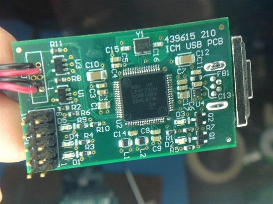
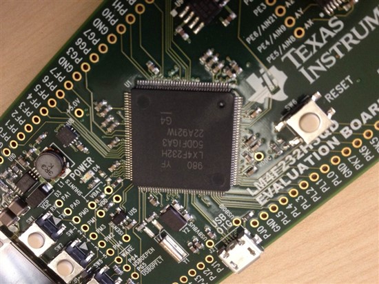
    In regards to the board, would you be open to posting a schematic? For the chip, is there any chance you can provide me with the complete label information on both chips from the EK-LM4F232 board you have, as well as the LM4F230 chip. I'm looking for the date code and the revision (A1 v. A3), because those will specify if certain errata apply on one and not the other. More specifically the following erratum might cause problems:


    Regards,

    Reagan

  • Hi Reagan,

    Thank you for your reply.  Below are pictures of the IC on my board and the IC on the eval board.  Attached is the schematic.

    On the schematic inside of the white box that didn't print is an LED and resistor attached to USB_VBUS.  PD4 is listed for both USBDP and USBDM but the pinout is correct, it's just a typo on the port pin label.  3.3V is applied externally and USB_MCU_PWR_EN is connected to 3.3V to turn on MCU_3.3V.  +5V is also applied externally and enabled when a host is detected.

    Thank you for your help.

    4382.USB Board Schematic.pdf


  • Anthony,

    Can you confirm that those were indeed the only software changes you made? In regards to the chip, the errata I was looking at is not an issue since your silicon is revision B0.

    For the hardware, there are two things I'm noticing at first glance: (1) the MOSFETs tied to PA0 and PA1 need gate drivers between them, and (2) is it the case that you have a separate 3.3uF capacitor on the VDDC lines? Generally it's the case that the VDDC pins are connected together and driven by one set of capacitors amounting to that ~3.3uF value. On this point though, it rides on whether or not those pins are connected internally. If they are, then the setup you have is a problem. Ultimately though, I think point (1) might be the problem, since you can't directly drive MOSFETs with the CMOS pins. The USB section seems fine.

    -Reagan


  • Reagan,

    Thank you for the review.  I removed the MOSFETs and still no luck.

    What I am noticing is that the ModeCallback function set up in USBStackModeSet() is not being called on all USB connect and disconnect events.  When I try the same code on the evaluation board, it works as it should.

    Also, I set a variable in ModeCallback to the returned tUSBMode and use that in my UART interrupt handler to do different things based on host or device mode.  However, when I set a breakpoint in the UART interrupt handler, the mode variable is not set to any recognizable USB mode and the interrupt never gets handled.  Again, this works properly on the eval board.

    If I hard code the device mode UART handler, it only handles UART RX to USB TX.  There seems to be a problem in the USB RX handler.  When I set a breakpoint and step through the handler, it never returns data from USBBufferRead() as the eval board does.

    I did verify that the UART works properly using a UART echo example.

    Should I keep the predefined symbol TARGET_IS_BLIZZARD_RA1 or does this need to be changed?  I have tried RA2 with no difference and RB0 does not work.  I am using StellarisWare 9453 and TI v5.0.3 compiler.

    Thank you,

    Anthony

  • I was able to take the usb_dev_bulk example from the ek-lm4f20xl and run it on my board.  I then took the usb_dev_serial program and it would not run on my board.  I get a FaultISR when the USB is plugged in.

  • Anthony,

    Please refer to another thread I've posted on @ http://e2e.ti.com/support/microcontrollers/stellaris_arm/f/471/p/260059/909615.aspx#909615.

    On there I've posted a link to a debugging app note and explained some basics of it as well. That will help guide the debugging effort, but if usb_dev_bulk ran fine, it seems like there might be an issue with the UART hardware.

    Regards,

    Reagan

  • Reagan,

    Thank you, I will check this out.  usb_dev_bulk uses the UART and I have executed a UART echo example so it seems like the UART hardware works.  I just need to figure out what is happening in the code.