This thread has been locked.

If you have a related question, please click the "Ask a related question" button in the top right corner. The newly created question will be automatically linked to this question.

BOOSTXL-SENSHUB on EK-LM4F120XL --> non working examples/sensors

Other Parts Discussed in Thread: TMP006, LMFLASHPROGRAMMER

Hi there,

I finally got the chance today to test my recently purchased BOOSTXL-SENSHUB on a new, fresh out of the box EK-LM4F120XL Stellaris Launchpad.

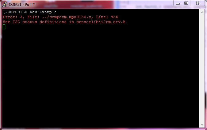
When testing all the samples provided I found that three of them were not working:

- Airmouse --> maybe related to my setup since I'm running CCS in an VMware Virtual machine (win7) on a MAC OS X host

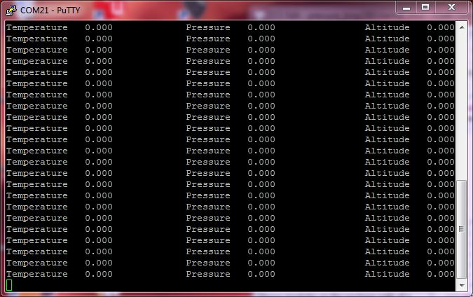
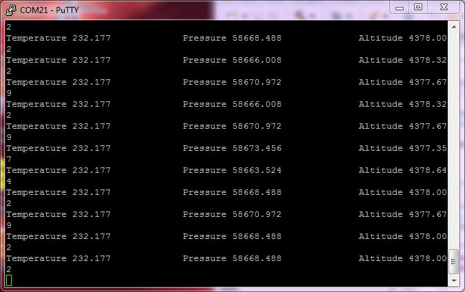
- BMP180 pressure sensor demo --> no air pressure! Don't worry: I'm still alive although there seems to be no air for me to breathe. 

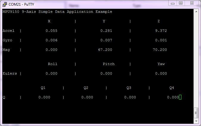
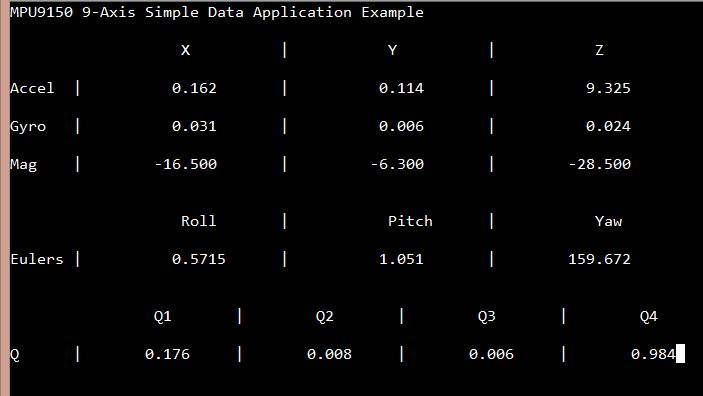
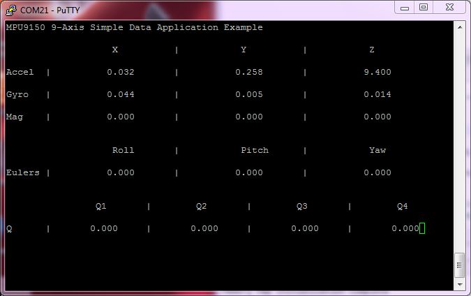
- MPU-9150 --> no MAG data --> no Euler Angles/Quaternations. Board is sitting flat on the table when capturing the screenshot (refer to z-axis value  = roughly 1g).

All other demos seems to run fine (on first view).

All examples should run on the EK-LM4F120XL without any modifications, right?

Do you have any other software to verify correct sensor/board operation (i.e. from factory end test)?

Is there a list of the I2C addresses in use? A scan with my quick&dirty I2C address scanner (part of my Stellaris I2C API, a polled I2C driver which can i.e. be found here http://e2e.ti.com/support/microcontrollers/tiva_arm/f/908/t/238721.aspx) gives me the list below:

0x77 --> BMP180
0x68 --> GYRO/ACC part of MPU-9150 - MAG is connected to the Auxiliary I2C bus of the MPU-9150 --> can not acknowledge until initialized for operation
0x44 --> ISL29023
0x41 --> TMP006
0x40 --> SHT21
0x00 --> unknown (?)

I have no glue which sensor also acknowledges address 0x00! Any idea?

Thank you for your answer! Hopefully I've not received a $49.99 brick!

Kind regards
aBUGSworstnightmare 

  • aBUGSworstnightmare said:
    I have no glue

    We do - multiple blends/sizes Loctite - over-flow our shelves...  (Adr 00 Clue - not so much - seems a poor choice for address...)

    Seriously - another very nice job - helpful to many - merci monsieur.

    Your "9 Axis" sample Accel reading "9.400" - so far from all others - seems mistaken or contrived...  (what's up w/that?)

    Haven't checked your pressure sensor spec - others we've used employed "Wheatstone bridge" - the care/handling of those outputs deserved attention.

    Thanks again - good luck.   (your camera "off-line?" - so helped your past posts!)  (although banished via rebrand exercise)

  • cb1_mobile said:
    Your "9 Axis" sample Accel reading "9.400" - so far from all others - seems mistaken or contrived...  (what's up w/that?)

    Hi cb1,

    this demo software (which is part of the new Tiva Launchpad examples) gives raw sensor data. The Accel Data in m/s^2 --> a value of 9.4 m/s^2 is the Z-Axis of the MPU-9150 when sitting level on my desk. 

    The ACC is uncalibrated --> it's value is not 1g (gravity) = 9,81m/s^2 as I would expect from a (perfectly) calibrated ACC.

    The MPU-9150 is a 'lil' beast' (I know what I'm talking about since I also use it on my C3ii INS Booster Pack) --> since no data comes from the MAG something most gone really bad (when the guys at TI did their homework and choose the right way to initialize the auxiliary I2C peripheral interface of the MPU; did not dig into their code if they use passthrough mode, but since they provide a AK8975 API I think they do it the 'easy way').

    The BMP180 is from Bosch Sensortec (very similiar to the BMP085 with some 'marketing spec polishing'). A guy from Bosch Sensortec (working in the headquarters in Reutlingen) told me that the BMP180 (as the BMP085) mostly die by  insufficient handling during reflow soldering. Mounting them with hot-air is a pain in the a**.

    Well, let's hear the opinion of somebody from TI.

    aBUGSworstnightmare

  • Mr. Nightmare,

    I believe there is a known timing issue on a initial power up of the boards in some cases.  Not sure that the sensors are up and ready by the time the MCU starts doing I2C transactions.  Still investigating.

    One confirmation is to try doing a simple button reset after powering up the system.  Usually then everything starts working as expected. 

    A not yet fully confirmed solution is to delay after I2CMInit.  At this point we have configured the pins and are ready to do I2C but this lets the bus sit idle while the BoosterPack finishes powering up and those sensors do their own init.

    We configure the MPU9150 to automatically do the transactions with the internal mag.  We use slave transfer (either 0 or 1) and 4.  The first transaction does a full read of the mag data into the 9150 data registers.  The second (slave transaction 4) does a simple write to initiate the next sample by the mag.  The slave transactions auto occur every fifth sample of the accel and gyro.  I am pretty sure we accept the default mag configuration and let the 9150 auto send trigger next mag sample and read mag sample into the 9150 data registers.  The M4 then does a single burst read of all the sensor data: accel, gyro and mag from the 9150 data registers. The mag data includes ST1 and ST2 which we use to confirm if the data is good.

    Another note. The current code does not do any attempts at I2C bus recovery.  When doing resets or debugging if the M4F resets during the wrong phase of an I2C transaction it can leave the bus in a stuck state.  The code is set currently to flash the red element of the RGB at 10hz and do nothing else if any I2C bus errors are reported by the I2C Master driver code.  On any example if you see 10 hz red on the RGB it means the i2c bus had an error and you need to reset or power cycle. There are ways to recover the bus but they were not implemented on these examples.

    I have no idea what would be ACK'ing address 0x00.  The I2C Address are #defined for each sensor at the top of the primary application file for each of the simple sensor applications.

    Dexter

  • Hi Dexter,

    Stellaris Dexter said:

    I believe there is a known timing issue on a initial power up of the boards in some cases.  Not sure that the sensors are up and ready by the time the MCU starts doing I2C transactions.  Still investigating.

    One confirmation is to try doing a simple button reset after powering up the system.  Usually then everything starts working as expected. 

    Confimed! But I needed multiple Button Resets to get a full set of data. Turning the board on all 3 axis while looking at the ACC values  gives data as expected (1g reading for each axis facing into gravity direction).

    Nevertheless, my BMP180 is still silent! I've connected a BMP085 I had on hand and get the data (Temp/Pressure/Alt). Since the BMP180 is the same device (only minor spec changes and another package) I assume that the BMP180 on my BOOSTXL-SENSHUB is faulty (since it gives no data; not even temperature).

    Any idea what to do? The other sensors (Light/Humidity/Temp) were nice, but I bought the boosterpack because it is a 10 DOF IMU (9axis + pressure). 

    Kind regards
    aBUGSworstnightmare 

  • @Dexter - had to memorialize, "Nightmare" (originality ++) and the care & detail (inside info) over-flowing your neat post.

    Very nice job - noted and appreciated - sure to help many.   Thank you...

  • Fixed up a couple of issues with the MPU9150 driver that i think are worth putting out now.

    Issue 1) We did not correctly issue a reset to the device during init.  MPU9150Init fills one buffer with the init data sequence and then transmits the other buffer over I2C.  This is resolved.

    Issue 2) On power up (and after any actual reset see issue 1) magnetometer data was not flowing from the device.  This was do to order of operations.  We first enabled I2C Master on the 9150 then brought device out of sleep mode.  This was done since that is the order the register appear in the 9150 memory map.  We now swap this order and bring device out of sleep mode (default reset state). Then enable I2C Master transactions.  

    Interaction with MPU9150 is now much more robust and appears to work out of power up or reset conditions much more reliably.

    Attached is modified MPU9150.c file.  Put this into TivaWare SensorLib and build sensor lib. then REBUILD any projects that use sensorlib so that the linker will bring in the changes.

    //*****************************************************************************
    //
    // mpu9150.c - Driver for the MPU9150 accelerometer, gyroscope, and
    //             magnetometer.
    //
    // Copyright (c) 2013 Texas Instruments Incorporated.  All rights reserved.
    // Software License Agreement
    // 
    // Texas Instruments (TI) is supplying this software for use solely and
    // exclusively on TI's microcontroller products. The software is owned by
    // TI and/or its suppliers, and is protected under applicable copyright
    // laws. You may not combine this software with "viral" open-source
    // software in order to form a larger program.
    // 
    // THIS SOFTWARE IS PROVIDED "AS IS" AND WITH ALL FAULTS.
    // NO WARRANTIES, WHETHER EXPRESS, IMPLIED OR STATUTORY, INCLUDING, BUT
    // NOT LIMITED TO, IMPLIED WARRANTIES OF MERCHANTABILITY AND FITNESS FOR
    // A PARTICULAR PURPOSE APPLY TO THIS SOFTWARE. TI SHALL NOT, UNDER ANY
    // CIRCUMSTANCES, BE LIABLE FOR SPECIAL, INCIDENTAL, OR CONSEQUENTIAL
    // DAMAGES, FOR ANY REASON WHATSOEVER.
    // 
    // This is part of revision 1.0 of the Tiva Firmware Development Package.
    //
    //*****************************************************************************
    
    #include <stdint.h>
    #include "sensorlib/hw_ak8975.h"
    #include "sensorlib/hw_mpu9150.h"
    #include "sensorlib/i2cm_drv.h"
    #include "sensorlib/ak8975.h"
    #include "sensorlib/mpu9150.h"
    
    //*****************************************************************************
    //
    //! \addtogroup mpu9150_api
    //! @{
    //
    //*****************************************************************************
    
    //*****************************************************************************
    //
    // The states of the MPU9150 state machine.
    //
    //*****************************************************************************
    #define MPU9150_STATE_IDLE      0           // State machine is idle
    #define MPU9150_STATE_LAST      1           // Last step in a sequence
    #define MPU9150_STATE_READ      2           // Waiting for read
    #define MPU9150_STATE_WRITE     3           // Waiting for write
    #define MPU9150_STATE_RMW       4           // Waiting for read modify write
    #define MPU9150_STATE_INIT_RESET                                              \
                                    5           // reset request issued.
    #define MPU9150_STATE_INIT_RESET_WAIT                                         \
                                    6           // polling wait for reset complete
    #define MPU9150_STATE_INIT_PWR_MGMT                                           \
                                    7           // wake up the device.
    #define MPU9150_STATE_INIT_USER_CTRL                                          \
                                    8           // init user control
    #define MPU9150_STATE_INIT_SAMPLE_RATE_CFG                                    \
                                    9           // init the sensors and filters
    #define MPU9150_STATE_INIT_I2C_SLAVE_DLY                                      \
                                    10          // set the ak8975 polling delay
    #define MPU9150_STATE_INIT_I2C_SLAVE_0                                        \
                                    11          // config ak8975 automatic read
    #define MPU9150_STATE_RD_DATA   12          // Waiting for data read
    
    //*****************************************************************************
    //
    // The factors used to convert the acceleration readings from the MPU9150 into
    // floating point values in meters per second squared.
    //
    // Values are obtained by taking the g conversion factors from the data sheet
    // and multiplying by 9.81 (1 g = 9.81 m/s^2).
    //
    //*****************************************************************************
    static const float g_fMPU9150AccelFactors[] =
    {
        0.0005985482,                           // Range = +/- 2 g (16384 lsb/g)
        0.0011970964,                           // Range = +/- 4 g (8192 lsb/g)
        0.0023941928,                           // Range = +/- 8 g (4096 lsb/g)
        0.0047883855                            // Range = +/- 16 g (2048 lsb/g)
    };
    
    //*****************************************************************************
    //
    // The factors used to convert the acceleration readings from the MPU9150 into
    // floating point values in radians per second.
    //
    // Values are obtained by taking the degree per second conversion factors
    // from the data sheet and then converting to radians per sec (1 degree =
    // 0.0174532925 radians).
    //
    //*****************************************************************************
    static const float g_fMPU9150GyroFactors[] =
    {
        1.3323124e-4,                           // Range = +/- 250 dps (131.0)
        2.6646248e-4,                           // Range = +/- 500 dps (65.5)
        5.3211258e-4,                           // Range = +/- 1000 dps (32.8)
        0.0010642252                            // Range = +/- 2000 dps (16.4)
    };
    
    //*****************************************************************************
    //
    // Converting sensor data to tesla (0.3 uT per LSB)
    //
    //*****************************************************************************
    #define CONVERT_TO_TESLA        0.0000003
    
    //*****************************************************************************
    //
    // The callback function that is called when I2C transations to/from the
    // MPU9150 have completed.
    //
    //*****************************************************************************
    static void
    MPU9150Callback(void *pvCallbackData, uint_fast8_t ui8Status)
    {
        tMPU9150 *psInst;
    
        //
        // Convert the instance data into a pointer to a tMPU9150 structure.
        //
        psInst = pvCallbackData;
    
        //
        // If the I2C master driver encountered a failure, force the state machine
        // to the idle state (which will also result in a callback to propagate the
        // error).
        //
        if(ui8Status != I2CM_STATUS_SUCCESS)
        {
            //
            // Handle the special case where device will send an address NACK
            // while it is still in the early portion of resetting itself.
            //
            if((ui8Status == I2CM_STATUS_ADDR_NACK) &&
               (psInst->ui8State == MPU9150_STATE_INIT_RESET_WAIT))
            {
                //
                // Device still in reset so keep polling this register.
                //
                psInst->uCommand.pui8Buffer[0] = MPU9150_O_PWR_MGMT_1;
                I2CMRead(psInst->psI2CInst, psInst->ui8Addr,
                         psInst->uCommand.pui8Buffer, 1, psInst->pui8Data, 1,
                         MPU9150Callback, psInst);
    
                //
                // Intentionally stay in this state to create polling effect.
                //
                return;
            }
            else
            {
                psInst->ui8State = MPU9150_STATE_IDLE;
            }
        }
    
        //
        // Determine the current state of the MPU9150 state machine.
        //
        switch(psInst->ui8State)
        {
            //
            // All states that trivially transition to IDLE, and all unknown
            // states.
            //
            case MPU9150_STATE_READ:
            case MPU9150_STATE_LAST:
            case MPU9150_STATE_RD_DATA:
            default:
            {
                //
                // The state machine is now idle.
                //
                psInst->ui8State = MPU9150_STATE_IDLE;
    
                //
                // Done.
                //
                break;
            }
    
            //
            // MPU9150 Device reset was issued
            //
            case MPU9150_STATE_INIT_RESET:
            {
                //
                // Issue a read of the status register to confirm reset is done.
                //
                psInst->uCommand.pui8Buffer[0] = MPU9150_O_PWR_MGMT_1;
                I2CMRead(psInst->psI2CInst, psInst->ui8Addr,
                         psInst->uCommand.pui8Buffer, 1, psInst->pui8Data, 1,
                         MPU9150Callback, psInst);
    
                psInst->ui8State = MPU9150_STATE_INIT_RESET_WAIT;
                break;
            }
    
            //
            // Status register was read, check if reset is done before proceeding.
            //
            case MPU9150_STATE_INIT_RESET_WAIT:
            {
                //
                // Check the value read back from status to determine if device
                // is still in reset or if it is ready.  Reset state for this
                // register is 0x40, which has sleep bit set.
                //
                if(psInst->pui8Data[0] != MPU9150_PWR_MGMT_1_SLEEP)
                {
                    //
                    // Device still in reset so begin polling this register.
                    //
                    psInst->uCommand.pui8Buffer[0] = MPU9150_O_PWR_MGMT_1;
                    I2CMRead(psInst->psI2CInst, psInst->ui8Addr,
                             psInst->uCommand.pui8Buffer, 1, psInst->pui8Data, 1,
                             MPU9150Callback, psInst);
    
                    //
                    // Intentionally stay in this state to create polling effect.
                    //
                }
                else
                {
                    //
                    // Device is out of reset, bring it out of sleep mode.
                    //
                    psInst->uCommand.pui8Buffer[0] = MPU9150_O_PWR_MGMT_1;
                    psInst->uCommand.pui8Buffer[1] = MPU9150_PWR_MGMT_1_CLKSEL_XG;
                    I2CMWrite(psInst->psI2CInst, psInst->ui8Addr,
                              psInst->uCommand.pui8Buffer, 2, MPU9150Callback,
                              psInst);
    
                    //
                    // Update state to show we are modifing user control and
                    // power management 1 regs.
                    //
                    psInst->ui8State = MPU9150_STATE_INIT_PWR_MGMT;
                }
                break;
            }
    
            //
            // Reset complete now take device out of sleep mode.
            //
            case MPU9150_STATE_INIT_PWR_MGMT:
            {
                psInst->uCommand.pui8Buffer[0] = MPU9150_O_USER_CTRL;
                psInst->uCommand.pui8Buffer[1] = MPU9150_USER_CTRL_I2C_MST_EN;
                I2CMWrite(psInst->psI2CInst, psInst->ui8Addr,
                      psInst->uCommand.pui8Buffer, 2, MPU9150Callback,
                          psInst);
    
                //
                // Update state to show we are modifing user control and
                // power management 1 regs.
                //
                psInst->ui8State = MPU9150_STATE_INIT_USER_CTRL;
    
                break;
            }
    
            //
            // Change to power mode complete, device is ready for configuration.
            //
            case MPU9150_STATE_INIT_USER_CTRL:
            {
                //
                // Load index 0 with the sample rate register number.
                //
                psInst->uCommand.pui8Buffer[0] = MPU9150_O_SMPLRT_DIV;
    
                //
                // Set sample rate to 50 hertz.  1000 hz / (1 + 19)
                //
                psInst->uCommand.pui8Buffer[1] = 19;
    
                I2CMWrite(psInst->psI2CInst, psInst->ui8Addr,
                          psInst->uCommand.pui8Buffer, 2, MPU9150Callback, psInst);
    
                //
                // update state to show are in process of configuring sensors.
                //
                psInst->ui8State = MPU9150_STATE_INIT_SAMPLE_RATE_CFG;
                break;
            }
    
            //
            // Sensor configuration is complete.
            //
            case MPU9150_STATE_INIT_SAMPLE_RATE_CFG:
            {
                //
                // Write the I2C Master delay control so we only sample the AK
                // every 5th time that we sample accel/gyro.  Delay Count itself
                // handled in next state.
                //
                psInst->uCommand.pui8Buffer[0] = MPU9150_O_I2C_MST_DELAY_CTRL;
                psInst->uCommand.pui8Buffer[1] =
                    (MPU9150_I2C_MST_DELAY_CTRL_I2C_SLV0_DLY_EN |
                     MPU9150_I2C_MST_DELAY_CTRL_I2C_SLV4_DLY_EN);
                I2CMWrite(psInst->psI2CInst, psInst->ui8Addr,
                          psInst->uCommand.pui8Buffer, 2, MPU9150Callback, psInst);
    
                //
                // Update state to show we are configuring i2c slave delay between
                // slave events.  Slave 0 and Slave 4 transaction only occur every
                // 5th sample cycle.
                //
                psInst->ui8State = MPU9150_STATE_INIT_I2C_SLAVE_DLY;
                break;
            }
    
            //
            // Master slave delay configuration complete.
            //
            case MPU9150_STATE_INIT_I2C_SLAVE_DLY:
            {
                //
                // Write the configuration for I2C master control clock 400khz
                // and wait for external sensor before asserting data ready
                //
                psInst->uCommand.pui8Buffer[0] = MPU9150_O_I2C_MST_CTRL;
                psInst->uCommand.pui8Buffer[1] =
                    (MPU9150_I2C_MST_CTRL_I2C_MST_CLK_400 |
                     MPU9150_I2C_MST_CTRL_WAIT_FOR_ES);
    
                //
                // Configure I2C Slave 0 for read of AK8975 (I2C Address 0x0C)
                // Start at AK8975 register status 1
                // Read 8 bytes and enable this slave transaction
                //
                psInst->uCommand.pui8Buffer[2] = MPU9150_I2C_SLV0_ADDR_RW | 0x0C;
                psInst->uCommand.pui8Buffer[3] = AK8975_O_ST1;
                psInst->uCommand.pui8Buffer[4] = MPU9150_I2C_SLV0_CTRL_EN | 0x08;
                I2CMWrite(psInst->psI2CInst, psInst->ui8Addr,
                          psInst->uCommand.pui8Buffer, 5, MPU9150Callback, psInst);
    
                //
                // Update state.  Now in process of configuring slave 0.
                //
                psInst->ui8State = MPU9150_STATE_INIT_I2C_SLAVE_0;
                break;
            }
    
            //
            // I2C slave 0 init complete.
            //
            case MPU9150_STATE_INIT_I2C_SLAVE_0:
            {
                //
                // Write the configuration for I2C Slave 4 transaction to AK8975
                // 0x0c is the AK8975 address on i2c bus.
                // we want to write the control register with the value for a
                // starting a single measurement.
                //
                psInst->uCommand.pui8Buffer[0] = MPU9150_O_I2C_SLV4_ADDR;
                psInst->uCommand.pui8Buffer[1] = 0x0C;
                psInst->uCommand.pui8Buffer[2] = AK8975_O_CNTL;
                psInst->uCommand.pui8Buffer[3] = AK8975_CNTL_MODE_SINGLE;
    
                //
                // Enable the SLV4 transaction and set the master delay to
                // 0x04 + 1.  This means the slave transactions with delay enabled
                // will run every fifth accel/gyro sample.
                //
                psInst->uCommand.pui8Buffer[4] = MPU9150_I2C_SLV4_CTRL_EN | 0x04;
                I2CMWrite(psInst->psI2CInst, psInst->ui8Addr,
                          psInst->uCommand.pui8Buffer, 5, MPU9150Callback, psInst);
    
                //
                // Update state.  Now in the final init state.
                //
                psInst->ui8State = MPU9150_STATE_LAST;
                break;
            }
    
            //
            // A write just completed
            //
            case MPU9150_STATE_WRITE:
            {
                //
                // Set the accelerometer and gyroscope ranges to the new values.
                // If the register was not modified, the values will be the same so
                // this has no effect.
                //
                psInst->ui8AccelAfsSel = psInst->ui8NewAccelAfsSel;
                psInst->ui8GyroFsSel = psInst->ui8NewGyroFsSel;
    
                //
                // The state machine is now idle.
                //
                psInst->ui8State = MPU9150_STATE_IDLE;
    
                //
                // Done.
                //
                break;
            }
    
            //
            // A read-modify-write just completed
            //
            case MPU9150_STATE_RMW:
            {
                //
                // See if the PWR_MGMT_1 register was just modified.
                //
                if(psInst->uCommand.sReadModifyWriteState.pui8Buffer[0] ==
                   MPU9150_O_PWR_MGMT_1)
                {
                    //
                    // See if a soft reset has been issued.
                    //
                    if(psInst->uCommand.sReadModifyWriteState.pui8Buffer[1] &
                       MPU9150_PWR_MGMT_1_DEVICE_RESET)
                    {
                        //
                        // Default range setting is +/- 2 g
                        //
                        psInst->ui8AccelAfsSel = 0;
                        psInst->ui8NewAccelAfsSel = 0;
    
                        //
                        // Default range setting is +/- 250 degrees/s
                        //
                        psInst->ui8GyroFsSel = 0;
                        psInst->ui8NewGyroFsSel = 0;
                    }
                }
    
                //
                // See if the GYRO_CONFIG register was just modified.
                //
                if(psInst->uCommand.sReadModifyWriteState.pui8Buffer[0] ==
                   MPU9150_O_GYRO_CONFIG)
                {
                    //
                    // Extract the FS_SEL from the GYRO_CONFIG register value.
                    //
                    psInst->ui8GyroFsSel =
                        ((psInst->uCommand.sReadModifyWriteState.pui8Buffer[1] &
                          MPU9150_GYRO_CONFIG_FS_SEL_M) >>
                         MPU9150_GYRO_CONFIG_FS_SEL_S);
                }
    
                //
                // See if the ACCEL_CONFIG register was just modified.
                //
                if(psInst->uCommand.sReadModifyWriteState.pui8Buffer[0] ==
                   MPU9150_O_ACCEL_CONFIG)
                {
                    //
                    // Extract the FS_SEL from the ACCEL_CONFIG register value.
                    //
                    psInst->ui8AccelAfsSel =
                        ((psInst->uCommand.sReadModifyWriteState.pui8Buffer[1] &
                          MPU9150_ACCEL_CONFIG_AFS_SEL_M) >>
                         MPU9150_ACCEL_CONFIG_AFS_SEL_S);
                }
    
                //
                // The state machine is now idle.
                //
                psInst->ui8State = MPU9150_STATE_IDLE;
    
                //
                // Done.
                //
                break;
            }
        }
    
        //
        // See if the state machine is now idle and there is a callback function.
        //
        if((psInst->ui8State == MPU9150_STATE_IDLE) && psInst->pfnCallback)
        {
            //
            // Call the application-supplied callback function.
            //
            psInst->pfnCallback(psInst->pvCallbackData, ui8Status);
        }
    }
    
    //*****************************************************************************
    //
    //! Initializes the MPU9150 driver.
    //!
    //! \param psInst is a pointer to the MPU9150 instance data.
    //! \param psI2CInst is a pointer to the I2C master driver instance data.
    //! \param ui8I2CAddr is the I2C address of the MPU9150 device.
    //! \param pfnCallback is the function to be called when the initialization has
    //! completed (can be \b NULL if a callback is not required).
    //! \param pvCallbackData is a pointer that is passed to the callback function.
    //!
    //! This function initializes the MPU9150 driver, preparing it for operation.
    //!
    //! \return Returns 1 if the MPU9150 driver was successfully initialized and 0
    //! if it was not.
    //
    //*****************************************************************************
    uint_fast8_t
    MPU9150Init(tMPU9150 *psInst, tI2CMInstance *psI2CInst,
                uint_fast8_t ui8I2CAddr, tSensorCallback *pfnCallback,
                void *pvCallbackData)
    {
        //
        // Initialize the MPU9150 instance structure.
        //
        psInst->psI2CInst = psI2CInst;
        psInst->ui8Addr = ui8I2CAddr;
    
        //
        // Save the callback information.
        //
        psInst->pfnCallback = pfnCallback;
        psInst->pvCallbackData = pvCallbackData;
    
        //
        // Default range setting is +/- 2 g
        //
        psInst->ui8AccelAfsSel = (MPU9150_ACCEL_CONFIG_AFS_SEL_2G >>
                                  MPU9150_ACCEL_CONFIG_AFS_SEL_S);
        psInst->ui8NewAccelAfsSel = (MPU9150_ACCEL_CONFIG_AFS_SEL_2G >>
                                     MPU9150_ACCEL_CONFIG_AFS_SEL_S);
    
        //
        // Default range setting is +/- 250 degrees/s
        //
        psInst->ui8GyroFsSel = (MPU9150_GYRO_CONFIG_FS_SEL_250 >>
                                MPU9150_GYRO_CONFIG_FS_SEL_S);
        psInst->ui8NewGyroFsSel = (MPU9150_GYRO_CONFIG_FS_SEL_250 >>
                                   MPU9150_GYRO_CONFIG_FS_SEL_S);
    
        //
        // Set the state to show we are initiating a reset.
        //
        psInst->ui8State = MPU9150_STATE_INIT_RESET;
    
        //
        // Load the buffer with command to perform device reset
        //
        psInst->uCommand.pui8Buffer[0] = MPU9150_O_PWR_MGMT_1;
        psInst->uCommand.pui8Buffer[1] = MPU9150_PWR_MGMT_1_DEVICE_RESET;
        if(I2CMWrite(psInst->psI2CInst, psInst->ui8Addr,
                     psInst->uCommand.pui8Buffer, 2, MPU9150Callback, psInst) == 0)
        {
            psInst->ui8State = MPU9150_STATE_IDLE;
            return(0);
        }
    
        //
        // Success
        //
        return(1);
    }
    
    //*****************************************************************************
    //
    //! Returns the pointer to the tAK8975 object
    //!
    //! \param psInst is a pointer to the MPU9150 instance data.
    //!
    //! The MPU9150 contains in internal AK8975 magnetometer.  To access data from
    //! that sensor, application should use this function to get a pointer to the
    //! tAK8975 object, and then use the AK8975 APIs.
    //!
    //! \return Returns the pointer to the tAK8975 object
    //
    //*****************************************************************************
    tAK8975 *
    MPU9150MagnetoInstGet(tMPU9150 *psInst)
    {
        return(&(psInst->sAK8975Inst));
    }
    
    //*****************************************************************************
    //
    //! Reads data from MPU9150 registers.
    //!
    //! \param psInst is a pointer to the MPU9150 instance data.
    //! \param ui8Reg is the first register to read.
    //! \param pui8Data is a pointer to the location to store the data that is
    //! read.
    //! \param ui16Count is the number of data bytes to read.
    //! \param pfnCallback is the function to be called when the data has been read
    //! (can be \b NULL if a callback is not required).
    //! \param pvCallbackData is a pointer that is passed to the callback function.
    //!
    //! This function reads a sequence of data values from consecutive registers in
    //! the MPU9150.
    //!
    //! \return Returns 1 if the write was successfully started and 0 if it was
    //! not.
    //
    //*****************************************************************************
    uint_fast8_t
    MPU9150Read(tMPU9150 *psInst, uint_fast8_t ui8Reg, uint8_t *pui8Data,
                uint_fast16_t ui16Count, tSensorCallback *pfnCallback,
                void *pvCallbackData)
    {
        //
        // Return a failure if the MPU9150 driver is not idle (in other words,
        // there is already an outstanding request to the MPU9150).
        //
        if(psInst->ui8State != MPU9150_STATE_IDLE)
        {
            return(0);
        }
    
        //
        // Save the callback information.
        //
        psInst->pfnCallback = pfnCallback;
        psInst->pvCallbackData = pvCallbackData;
    
        //
        // Move the state machine to the wait for read state.
        //
        psInst->ui8State = MPU9150_STATE_READ;
    
        //
        // Read the requested registers from the MPU9150.
        //
        psInst->uCommand.pui8Buffer[0] = ui8Reg;
        if(I2CMRead(psInst->psI2CInst, psInst->ui8Addr,
                    psInst->uCommand.pui8Buffer, 1, pui8Data, ui16Count,
                    MPU9150Callback, psInst) == 0)
        {
            //
            // The I2C write failed, so move to the idle state and return a
            // failure.
            //
            psInst->ui8State = MPU9150_STATE_IDLE;
            return(0);
        }
    
        //
        // Success.
        //
        return(1);
    }
    
    //*****************************************************************************
    //
    //! Writes data to MPU9150 registers.
    //!
    //! \param psInst is a pointer to the MPU9150 instance data.
    //! \param ui8Reg is the first register to write.
    //! \param pui8Data is a pointer to the data to write.
    //! \param ui16Count is the number of data bytes to write.
    //! \param pfnCallback is the function to be called when the data has been
    //! written (can be \b NULL if a callback is not required).
    //! \param pvCallbackData is a pointer that is passed to the callback function.
    //!
    //! This function writes a sequence of data values to consecutive registers in
    //! the MPU9150.  The first byte of the \e pui8Data buffer contains the value
    //! to be written into the \e ui8Reg register, the second value contains the
    //! data to be written into the next register, and so on.
    //!
    //! \return Returns 1 if the write was successfully started and 0 if it was
    //! not.
    //
    //*****************************************************************************
    uint_fast8_t
    MPU9150Write(tMPU9150 *psInst, uint_fast8_t ui8Reg, const uint8_t *pui8Data,
                 uint_fast16_t ui16Count, tSensorCallback *pfnCallback,
                 void *pvCallbackData)
    {
        //
        // Return a failure if the MPU9150 driver is not idle (in other words,
        // there is already an outstanding request to the MPU9150).
        //
        if(psInst->ui8State != MPU9150_STATE_IDLE)
        {
            return(0);
        }
    
        //
        // Save the callback information.
        //
        psInst->pfnCallback = pfnCallback;
        psInst->pvCallbackData = pvCallbackData;
    
        //
        // See if the PWR_MGMT_1 register is being written.
        //
        if((ui8Reg <= MPU9150_O_PWR_MGMT_1) &&
           ((ui8Reg + ui16Count) > MPU9150_O_PWR_MGMT_1))
        {
            //
            // See if a soft reset is being requested.
            //
            if(pui8Data[ui8Reg - MPU9150_O_PWR_MGMT_1] &
               MPU9150_PWR_MGMT_1_DEVICE_RESET)
            {
                //
                // Default range setting is +/- 2 g.
                //
                psInst->ui8NewAccelAfsSel = 0;
    
                //
                // Default range setting is +/- 250 degrees/s.
                //
                psInst->ui8NewGyroFsSel = 0;
            }
        }
    
        //
        // See if the GYRO_CONFIG register is being written.
        //
        if((ui8Reg <= MPU9150_O_GYRO_CONFIG) &&
           ((ui8Reg + ui16Count) > MPU9150_O_GYRO_CONFIG))
        {
            //
            // Extract the FS_SEL from the GYRO_CONFIG register value.
            //
            psInst->ui8NewGyroFsSel = ((pui8Data[ui8Reg - MPU9150_O_GYRO_CONFIG] &
                                        MPU9150_GYRO_CONFIG_FS_SEL_M) >>
                                       MPU9150_GYRO_CONFIG_FS_SEL_S);
        }
    
        //
        // See if the ACCEL_CONFIG register is being written.
        //
        if((ui8Reg <= MPU9150_O_ACCEL_CONFIG) &&
           ((ui8Reg + ui16Count) > MPU9150_O_ACCEL_CONFIG))
        {
            //
            // Extract the AFS_SEL from the ACCEL_CONFIG register value.
            //
            psInst->ui8NewAccelAfsSel =
                ((pui8Data[ui8Reg - MPU9150_O_ACCEL_CONFIG] &
                  MPU9150_ACCEL_CONFIG_AFS_SEL_M) >>
                 MPU9150_ACCEL_CONFIG_AFS_SEL_S);
        }
    
        //
        // Move the state machine to the wait for write state.
        //
        psInst->ui8State = MPU9150_STATE_WRITE;
    
        //
        // Write the requested registers to the MPU9150.
        //
        if(I2CMWrite8(&(psInst->uCommand.sWriteState), psInst->psI2CInst,
                      psInst->ui8Addr, ui8Reg, pui8Data, ui16Count,
                      MPU9150Callback, psInst) == 0)
        {
            //
            // The I2C write failed, so move to the idle state and return a
            // failure.
            //
            psInst->ui8State = MPU9150_STATE_IDLE;
            return(0);
        }
    
        //
        // Success.
        //
        return(1);
    }
    
    //*****************************************************************************
    //
    //! Performs a read-modify-write of a MPU9150 register.
    //!
    //! \param psInst is a pointer to the MPU9150 instance data.
    //! \param ui8Reg is the register to modify.
    //! \param ui8Mask is the bit mask that is ANDed with the current register
    //! value.
    //! \param ui8Value is the bit mask that is ORed with the result of the AND
    //! operation.
    //! \param pfnCallback is the function to be called when the data has been
    //! changed (can be \b NULL if a callback is not required).
    //! \param pvCallbackData is a pointer that is passed to the callback function.
    //!
    //! This function changes the value of a register in the MPU9150 via a
    //! read-modify-write operation, allowing one of the fields to be changed
    //! without disturbing the other fields.  The \e ui8Reg register is read, ANDed
    //! with \e ui8Mask, ORed with \e ui8Value, and then written back to the
    //! MPU9150.
    //!
    //! \return Returns 1 if the read-modify-write was successfully started and 0
    //! if it was not.
    //
    //*****************************************************************************
    uint_fast8_t
    MPU9150ReadModifyWrite(tMPU9150 *psInst, uint_fast8_t ui8Reg,
                           uint_fast8_t ui8Mask, uint_fast8_t ui8Value,
                           tSensorCallback *pfnCallback, void *pvCallbackData)
    {
        //
        // Return a failure if the MPU9150 driver is not idle (in other words,
        // there is already an outstanding request to the MPU9150).
        //
        if(psInst->ui8State != MPU9150_STATE_IDLE)
        {
            return(0);
        }
    
        //
        // Save the callback information.
        //
        psInst->pfnCallback = pfnCallback;
        psInst->pvCallbackData = pvCallbackData;
    
        //
        // Move the state machine to the wait for read-modify-write state.
        //
        psInst->ui8State = MPU9150_STATE_RMW;
    
        //
        // Submit the read-modify-write request to the MPU9150.
        //
        if(I2CMReadModifyWrite8(&(psInst->uCommand.sReadModifyWriteState),
                                psInst->psI2CInst, psInst->ui8Addr, ui8Reg,
                                ui8Mask, ui8Value, MPU9150Callback, psInst) == 0)
        {
            //
            // The I2C read-modify-write failed, so move to the idle state and
            // return a failure.
            //
            psInst->ui8State = MPU9150_STATE_IDLE;
            return(0);
        }
    
        //
        // Success.
        //
        return(1);
    }
    
    //*****************************************************************************
    //
    //! Reads the accelerometer and gyroscope data from the MPU9150 and the
    //! magnetometer data from the on-chip aK8975.
    //!
    //! \param psInst is a pointer to the MPU9150 instance data.
    //! \param pfnCallback is the function to be called when the data has been read
    //! (can be \b NULL if a callback is not required).
    //! \param pvCallbackData is a pointer that is passed to the callback function.
    //!
    //! This function initiates a read of the MPU9150 data registers.  When the
    //! read has completed (as indicated by calling the callback function), the new
    //! readings can be obtained via:
    //!
    //! - MPU9150DataAccelGetRaw()
    //! - MPU9150DataAccelGetFloat()
    //! - MPU9150DataGyroGetRaw()
    //! - MPU9150DataGyroGetFloat()
    //! - MPU9150DataMagnetoGetRaw()
    //! - MPU9150DataMagnetoGetFloat()
    //!
    //! \return Returns 1 if the read was successfully started and 0 if it was not.
    //
    //*****************************************************************************
    uint_fast8_t
    MPU9150DataRead(tMPU9150 *psInst, tSensorCallback *pfnCallback,
                    void *pvCallbackData)
    {
        //
        // Return a failure if the MPU9150 driver is not idle (in other words,
        // there is already an outstanding request to the MPU9150).
        //
        if(psInst->ui8State != MPU9150_STATE_IDLE)
        {
            return(0);
        }
    
        //
        // Save the callback information.
        //
        psInst->pfnCallback = pfnCallback;
        psInst->pvCallbackData = pvCallbackData;
    
        //
        // Move the state machine to the wait for data read state.
        //
        psInst->ui8State = MPU9150_STATE_RD_DATA;
    
        //
        // Read the data registers from the MPU9150.
        //
        // (ACCEL_XOUT_H(0x3B) -> GYRO_ZOUT_L(0x48) = 14 bytes
        // Grab Ext Sens Data as well for another 8 bytes.  ST1 + Mag Data + ST2
        //
        psInst->uCommand.pui8Buffer[0] = MPU9150_O_ACCEL_XOUT_H;
        if(I2CMRead(psInst->psI2CInst, psInst->ui8Addr,
                    psInst->uCommand.pui8Buffer, 1, psInst->pui8Data, 22,
                    MPU9150Callback, psInst) == 0)
        {
            //
            // The I2C read failed, so move to the idle state and return a failure.
            //
            psInst->ui8State = MPU9150_STATE_IDLE;
            return(0);
        }
    
        //
        // Success.
        //
        return(1);
    }
    
    //*****************************************************************************
    //
    //! Gets the raw accelerometer data from the most recent data read.
    //!
    //! \param psInst is a pointer to the MPU9150 instance data.
    //! \param pui16AccelX is a pointer to the value into which the raw X-axis
    //! accelerometer data is stored.
    //! \param pui16AccelY is a pointer to the value into which the raw Y-axis
    //! accelerometer data is stored.
    //! \param pui16AccelZ is a pointer to the value into which the raw Z-axis
    //! accelerometer data is stored.
    //!
    //! This function returns the raw accelerometer data from the most recent data
    //! read.  The data is not manipulated in any way by the driver.  If any of the
    //! output data pointers are \b NULL, the corresponding data is not provided.
    //!
    //! \return None.
    //
    //*****************************************************************************
    void
    MPU9150DataAccelGetRaw(tMPU9150 *psInst, uint_fast16_t *pui16AccelX,
                           uint_fast16_t *pui16AccelY, uint_fast16_t *pui16AccelZ)
    {
        //
        // Return the raw accelerometer values.
        //
        if(pui16AccelX)
        {
            *pui16AccelX = (psInst->pui8Data[0] << 8) | psInst->pui8Data[1];
        }
        if(pui16AccelY)
        {
            *pui16AccelY = (psInst->pui8Data[2] << 8) | psInst->pui8Data[3];
        }
        if(pui16AccelZ)
        {
            *pui16AccelZ = (psInst->pui8Data[4] << 8) | psInst->pui8Data[5];
        }
    }
    
    //*****************************************************************************
    //
    //! Gets the accelerometer data from the most recent data read.
    //!
    //! \param psInst is a pointer to the MPU9150 instance data.
    //! \param pfAccelX is a pointer to the value into which the X-axis
    //! accelerometer data is stored.
    //! \param pfAccelY is a pointer to the value into which the Y-axis
    //! accelerometer data is stored.
    //! \param pfAccelZ is a pointer to the value into which the Z-axis
    //! accelerometer data is stored.
    //!
    //! This function returns the accelerometer data from the most recent data
    //! read, converted into meters per second squared (m/s^2).  If any of the
    //! output data pointers are \b NULL, the corresponding data is not provided.
    //!
    //! \return None.
    //
    //*****************************************************************************
    void
    MPU9150DataAccelGetFloat(tMPU9150 *psInst, float *pfAccelX, float *pfAccelY,
                             float *pfAccelZ)
    {
        float fFactor;
    
        //
        // Get the acceleration conversion factor for the current data format.
        //
        fFactor = g_fMPU9150AccelFactors[psInst->ui8AccelAfsSel];
    
        //
        // Convert the accelerometer values into m/sec^2
        //
        if(pfAccelX)
        {
            *pfAccelX = ((float)(int16_t)((psInst->pui8Data[0] << 8) |
                                          psInst->pui8Data[1]) * fFactor);
        }
        if(pfAccelY)
        {
            *pfAccelY = ((float)(int16_t)((psInst->pui8Data[2] << 8) |
                                          psInst->pui8Data[3]) * fFactor);
        }
        if(pfAccelZ)
        {
            *pfAccelZ = ((float)(int16_t)((psInst->pui8Data[4] << 8) |
                                          psInst->pui8Data[5]) * fFactor);
        }
    }
    
    //*****************************************************************************
    //
    //! Gets the raw gyroscope data from the most recent data read.
    //!
    //! \param psInst is a pointer to the MPU9150 instance data.
    //! \param pui16GyroX is a pointer to the value into which the raw X-axis
    //! gyroscope data is stored.
    //! \param pui16GyroY is a pointer to the value into which the raw Y-axis
    //! gyroscope data is stored.
    //! \param pui16GyroZ is a pointer to the value into which the raw Z-axis
    //! gyroscope data is stored.
    //!
    //! This function returns the raw gyroscope data from the most recent data
    //! read.  The data is not manipulated in any way by the driver.  If any of the
    //! output data pointers are \b NULL, the corresponding data is not provided.
    //!
    //! \return None.
    //
    //*****************************************************************************
    void
    MPU9150DataGyroGetRaw(tMPU9150 *psInst, uint_fast16_t *pui16GyroX,
                          uint_fast16_t *pui16GyroY, uint_fast16_t *pui16GyroZ)
    {
        //
        // Return the raw gyroscope values.
        //
        if(pui16GyroX)
        {
            *pui16GyroX = (psInst->pui8Data[8] << 8) | psInst->pui8Data[9];
        }
        if(pui16GyroY)
        {
            *pui16GyroY = (psInst->pui8Data[10] << 8) | psInst->pui8Data[11];
        }
        if(pui16GyroZ)
        {
            *pui16GyroZ = (psInst->pui8Data[12] << 8) | psInst->pui8Data[13];
        }
    }
    
    //*****************************************************************************
    //
    //! Gets the gyroscope data from the most recent data read.
    //!
    //! \param psInst is a pointer to the MPU9150 instance data.
    //! \param pfGyroX is a pointer to the value into which the X-axis
    //! gyroscope data is stored.
    //! \param pfGyroY is a pointer to the value into which the Y-axis
    //! gyroscope data is stored.
    //! \param pfGyroZ is a pointer to the value into which the Z-axis
    //! gyroscope data is stored.
    //!
    //! This function returns the gyroscope data from the most recent data read,
    //! converted into radians per second.  If any of the output data pointers are
    //! \b NULL, the corresponding data is not provided.
    //!
    //! \return None.
    //
    //*****************************************************************************
    void
    MPU9150DataGyroGetFloat(tMPU9150 *psInst, float *pfGyroX, float *pfGyroY,
                            float *pfGyroZ)
    {
        float fFactor;
        int16_t i16Temp;
    
        //
        // Get the gyroscope conversion factor for the current data format.
        //
        fFactor = g_fMPU9150GyroFactors[psInst->ui8GyroFsSel];
    
        //
        // Convert the gyroscope values into rad/sec
        //
        if(pfGyroX)
        {
            i16Temp = (int16_t)psInst->pui8Data[8];
            i16Temp <<= 8;
            i16Temp += psInst->pui8Data[9];
            *pfGyroX = (float)i16Temp;
            *pfGyroX *= fFactor;
        }
        if(pfGyroY)
        {
            i16Temp = (int16_t)psInst->pui8Data[10];
            i16Temp <<= 8;
            i16Temp += psInst->pui8Data[11];
            *pfGyroY = (float)i16Temp;
            *pfGyroY *= fFactor;
        }
        if(pfGyroZ)
        {
            i16Temp = (int16_t)psInst->pui8Data[12];
            i16Temp <<= 8;
            i16Temp += psInst->pui8Data[13];
            *pfGyroZ = (float)i16Temp;
            *pfGyroZ *= fFactor;
        }
    }
    
    //*****************************************************************************
    //
    //! Gets the raw magnetometer data from the most recent data read.
    //!
    //! \param psInst is a pointer to the MPU9150 instance data.
    //! \param pui16MagnetoX is a pointer to the value into which the raw X-axis
    //! magnetometer data is stored.
    //! \param pui16MagnetoY is a pointer to the value into which the raw Y-axis
    //! magnetometer data is stored.
    //! \param pui16MagnetoZ is a pointer to the value into which the raw Z-axis
    //! magnetometer data is stored.
    //!
    //! This function returns the raw magnetometer data from the most recent data
    //! read.  The data is not manipulated in any way by the driver.  If any of the
    //! output data pointers are \b NULL, the corresponding data is not provided.
    //!
    //! \return None.
    //
    //*****************************************************************************
    void
    MPU9150DataMagnetoGetRaw(tMPU9150 *psInst, uint_fast16_t *pui16MagnetoX,
                             uint_fast16_t *pui16MagnetoY,
                             uint_fast16_t *pui16MagnetoZ)
    {
        uint8_t *pui8ExtSensData;
    
        pui8ExtSensData = &(psInst->pui8Data[14]);
    
        //
        // Return the raw magnetometer values.
        //
        if(pui16MagnetoX)
        {
            *pui16MagnetoX = (pui8ExtSensData[2] << 8) | pui8ExtSensData[1];
        }
        if(pui16MagnetoY)
        {
            *pui16MagnetoY = (pui8ExtSensData[4] << 8) | pui8ExtSensData[3];
        }
        if(pui16MagnetoZ)
        {
            *pui16MagnetoZ = (pui8ExtSensData[6] << 8) | pui8ExtSensData[5];
        }
    }
    
    //*****************************************************************************
    //
    //! Gets the magnetometer data from the most recent data read.
    //!
    //! \param psInst is a pointer to the MPU9150 instance data.
    //! \param pfMagnetoX is a pointer to the value into which the X-axis
    //! magnetometer data is stored.
    //! \param pfMagnetoY is a pointer to the value into which the Y-axis
    //! magnetometer data is stored.
    //! \param pfMagnetoZ is a pointer to the value into which the Z-axis
    //! magnetometer data is stored.
    //!
    //! This function returns the magnetometer data from the most recent data read,
    //! converted into tesla.  If any of the output data pointers are
    //! \b NULL, the corresponding data is not provided.
    //!
    //! \return None.
    //
    //*****************************************************************************
    void
    MPU9150DataMagnetoGetFloat(tMPU9150 *psInst, float *pfMagnetoX,
                               float *pfMagnetoY, float *pfMagnetoZ)
    {
        int16_t *pi16Data;
    
        pi16Data = (int16_t *)(psInst->pui8Data + 15);
    
        //
        // Convert the magnetometer values into floating-point tesla values.
        //
        if(pfMagnetoX)
        {
            *pfMagnetoX = (float)pi16Data[0];
            *pfMagnetoX *= CONVERT_TO_TESLA;
        }
        if(pfMagnetoY)
        {
            *pfMagnetoY = (float)pi16Data[1];
            *pfMagnetoY *= CONVERT_TO_TESLA;
        }
        if(pfMagnetoZ)
        {
            *pfMagnetoZ = (float)pi16Data[2];
            *pfMagnetoZ *= CONVERT_TO_TESLA;
        }
    }
    
    //*****************************************************************************
    //
    // Close the Doxygen group.
    //! @}
    //
    //*****************************************************************************
    

    Dexter

  • Hi Dexter,

    thank you for the information and the update of the MPU-9150 driver.

    Well, I'm sad to say but I'm facing issues with your latest driver version! Here's what I did:

    1.) Download your attached source file 6862.mpu9150.c, renamed it to mpu9150.c and droped it into the sensorlib-folder (replacing the old one)

    2.) imported and rebuild sensorlib

    3.) Cleaned 'compdcm_mpu9150'-project and build it

    4.) Flash it to LM4F120 Launchpad

    5.) Running the App (Resume (F8))

    Here's what I get:

    The terminal window will show the error message shown above!

    O.K.! So far -  so good!

    6.) stopping the active debug session

    7.) Reseting the Launchpad by Hardware reset (as we need to do before) results in:

    MPU-9150 gives data for ACC/GYRO/MAG, but neither Eulers nor Quaternations were calculated (outputted on the terminal). Several attemps to (HW-) reset the Launchpad always show the above picture.

    Conclusion:

    I can't confirm that your latest MPU9150.c solves the issues with MPU-9150! From my point of view the startup is better (HW-Reset), but there seem to be some (more) bugs since the app throws an error message after starting it for the first time and, in addition, it will not calculate Eulers/Q (with the old one the data was present afar one/multiple HW-reset).

    Rgds

    aBUGSworstnightmare 

  • Downloaded and installed a fresh copy of TivaWare from the web to replicate this issue.  This behavior is actually a side effect of the "fix".  By virtue of the way the mag is set up it only gets new mag data after a sample or two of the accel/gyro.  The very first accel data sample you get triggers the mag to sample which data is then collected the next time around.

    End result is that mag data is 0.0f when you call CompDCMStart and this does not properly init the DCM.  I added the if(pfMag[0] != 0.0f) statement to the application compdcm_mpu9150.c code and this fixes the issue for now.  We'll try to make a cleaner solution for the full release.  A similar change will be needed for airmouse.

    if(ui32CompDCMStarted == 0)
    {
    //
    // Set flag indicating that DCM is started.
    // Perform the seeding of the DCM with the first data set.
    //
    if(pfMag[0] != 0.0f)
    {
    ui32CompDCMStarted = 1;
    CompDCMMagnetoUpdate(&g_sCompDCMInst, pfMag[0], pfMag[1],
    pfMag[2]);
    CompDCMAccelUpdate(&g_sCompDCMInst, pfAccel[0], pfAccel[1],
    pfAccel[2]);
    CompDCMGyroUpdate(&g_sCompDCMInst, pfGyro[0], pfGyro[1],
    pfGyro[2]);
    CompDCMStart(&g_sCompDCMInst);
    }
    }

  • aBUGSworstnightmare said:

    Nevertheless, my BMP180 is still silent! I've connected a BMP085 I had on hand and get the data (Temp/Pressure/Alt). Since the BMP180 is the same device (only minor spec changes and another package) I assume that the BMP180 on my BOOSTXL-SENSHUB is faulty (since it gives no data; not even temperature).

    I can confirm that the BMP180 on my newly-received Sensor Hub is not functional.  Although I'm using an EXP430G2 with my own software, the code is proven to work with both BMP085 and BMP180s.  With the SensHub the code reads plausible configuration information, but the raw temperature reading is always 0xFFFF, and the raw pressure reading is 0x8040 with zero oversampling (the high bit gets shifted as appropriate when oversampling).

    Based on other comments I'm guessing the chip was mishandled during assembly.  I'm just hoping the remaining sensors work.  (I don't intend to use TivaWare so don't care if the supplied software is wrong.)

  • Peter,

    Thanks for the report.  Since you are getting data (though wrong) from the device this suggests you may have a different error from that found by aBUGSworstnightmare.

    I am going to pull a couple of samples from stock to spot check the BMP180 and the board assembly.

    Do you have a logic analyzer or o-scope? Can you confirm that the your code and the logic analyzer agree regarding the data on the I2C bus?

    Dexter

    Dexter

  • Yes, my Saleae Logic8 and my code agree on the values being read over the bus.  It's only raw measurement values (not the calibration block at a different address) that are completely unrealistic, suggesting a sensor failure not bus errors.

  • Stellaris Dexter said:
    I am going to pull a couple of samples from stock to spot check the BMP180 and the board assembly.

    Hi Dexter,

    yes, I think you should do this immediately to hunt down the issue with the BMP180.

    I've tested a third boosterpack today and the results were shown below:

    - 1st one tested: no data from BMP180 (reason for starting this tread)

    total fail!

    - 2nd one tested: data is as expected (see below)

    Data from a working BMP180; at least Temp and Alt represent the correct figures; can't verify Pressure reading since I'm not able to measure it.

    - 3th one tested: Gives some data, but data is static --> device is not working (needs to be verified with logic analyser)

    Data is all static (except some minor variation) --> Heated it up (with my desk lap) --> Temp is not increasing --> device is damaged! 

    Conclusion: BMP180 on two out of my three boosterpacks were damaged!

    Since the boosterpack has neither a lot nor a serial number I can't give you more details which could help you in locating the problem (and there must be one).

    Rgds
    aBUGSworstnightmare 

  • I pulled four units from stock and tested the BMP180 with the TivaWare 1.0 pressure_bmp180 application.

    All four worked correctly.

    I'll work offline with those affected to arrange returns and possible replacements.

    Dexter

  • I am trying to get basic examples in Sensor hub to work on the older version of EK-LM4F120XL. 

    However, I am getting this error message when I debug the program in CCS.

    The below output is coming through the debug port. (virtual com port)

    Air Mouse Application

    Error: 1, File: ../motion.c, Line: 901
    See I2C status definitions in utils\i2cm_drv.h
    Error: 1, File: ../motion.c, Line: 917
    See I2C status definitions in utils\i2cm_drv.h
    Error: 1, File: ../motion.c, Line: 932
    See I2C status definitions in utils\i2cm_drv.h

    Any thoughts what may be going wrong?

    There is an error in eclipse which says I am using a compiler version 4.9.8 while the airmouse source was written in 5.0.3.

    However my CCS does not update to 5.0.3 since the update program shows another error during the update operation.

    Also, I wonder how the compiler might cause such a problem with source.

    Any help appreciated.

  • The airmouse example is tested for each release for each compiler on the EK-LM4F120XL at least for TivaWare C Series 1.0.  One thing to try which would eliminate your compiler differences is to use the binary files that ship with TivaWare.  You can use the binary for any of the supported compilers.  Use LMFlashProgrammer to load the binary file to the LaunchPad.  We test these binaries as a part of the release process.  On good hardware they will work.  This will make sure your hardware is working.

    As mentioned earlier we have found that a reset button press is sometimes required to get the sensor hub and the MCU in sync.  This is being fixed for TivaWare 1.1.

    The compiler difference can change many things from timing to the implementation and optimization of our code.  I would suggest doing a complete CCS uninstall and then re-install from.  Without examing in detail the generated assembly/binary code it may or may not be contributing to your difficulty.  Strongly suggest to use the same or newer version.

    Airmouse and compdcm_mpu9150 both use the same sensor and drivers try both of these applications.

    Dexter

  • How to do the calibration to get correct fusion result ? 

    I can simply perform that with the board flat level to calibrate

    1. Accel (g) - x:0 , y:0, z:1 

    2. Gyro - x:0, y:0, z:0

    3. Mag - offset

    But after that, when I only roll or pitch the device, the yaw is moving, also.

    I think the compass is not well calibrated.

    How to do the complete calibrate to get the correct Roll, Pitch and Yaw moment?

  • We do not have at this time calibration example code.

    The magnetometer is very sensitive to electronics and magnetic material in the area.  Make sure the sensor hub is as far away as possible from other devices and steel or other magnetic interference.

    Dexter

  • Here is my testing setup, I think it's quite normal.

    Where can I reference the calibration example code? especially the compass... thanks!

  • Hi JackRose,

        I am just curious to know, what kit is that?

    -kel


  • I think this post will be of your interest. http://e2e.ti.com/support/microcontrollers/tiva_arm/f/908/p/285768/1031737.aspx#1031737
  • seems it's the knowing issue do not fix yet ...

  • I have problems with the BMP180. The temperature reading is correct, I got ~ 26 degree, heated it up and the temp is increasing. I have problems only with the pressure: I get ~ 37300 Pa, altitude ~ 7677m, which are, of course, wrong data:

    Any idea on what's happening?

  • I found a bug in sensorlib, in function BMP180DataPressureGetFloat():

    fUT = (float)(int16_t)((psInst->pui8Data[0] << 8) |
                               psInst->pui8Data[1]);

    In this line int16_t must be replaced with int32_t. In my case, the uncompensated temperature value was 0x83FC, so with int16_t this will be a negative value...

    Now, the pressure is 981,1 hPa and altitude is 272 m, data which are quite close to the reality.

  • Hi tibcsi,

    I will let our software team know so they can look into fixing the bug.

    Thank you,

    David