This thread has been locked.

If you have a related question, please click the "Ask a related question" button in the top right corner. The newly created question will be automatically linked to this question.

Pin labeled ACTIVE on Tiva C Series / Stellaris Launchpad

Hi,

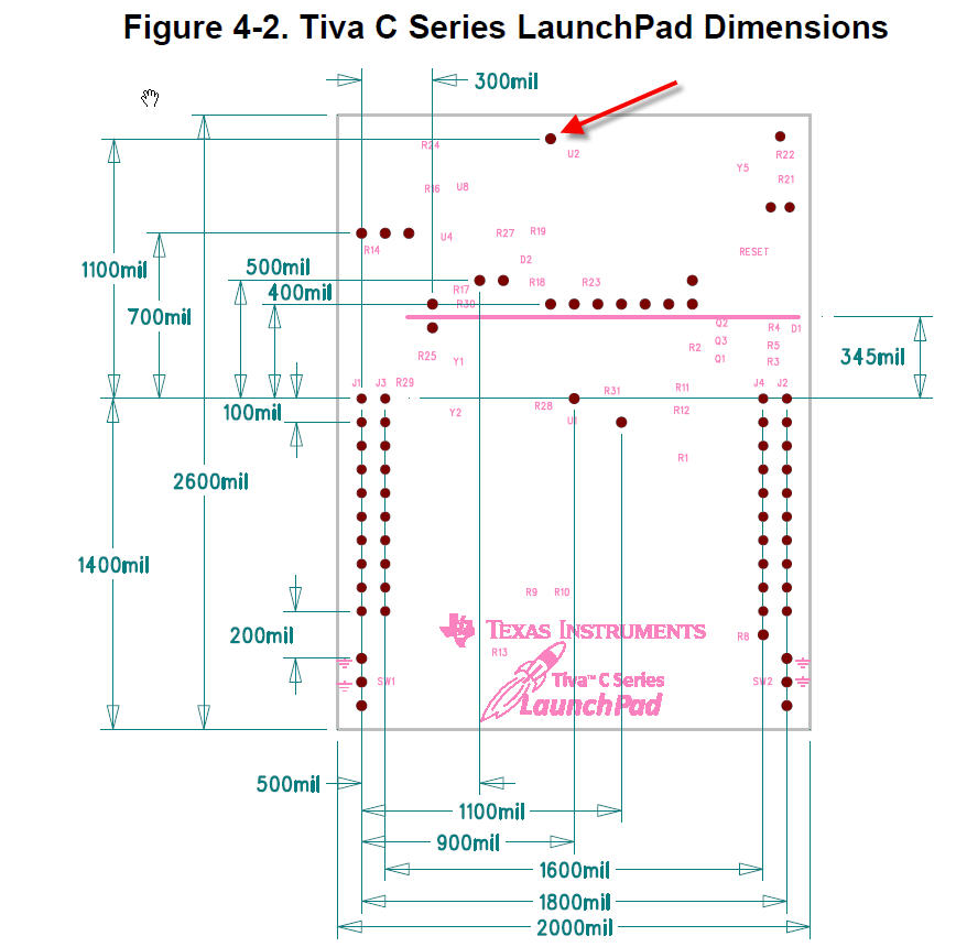
there is a pin labeled ACTIVE on the TIVA/STELLARIS Launchpads (refer to picture; marked by red arrow).

Unforntunately, I'm unable to find any information on this pin and it's function since it's neither shown in the schematics (hence it's named H15 there but not labeled) nor documented in the user's manual.

So, what is it/could it be used for?
 Is it i.e. used to signalize debug(out) activities (there's such an LED on the Stellaris EVMs)? If so, is it possible to connect it to an LED (i.e. via jumpwire to J4.1 = PF2= RGB Blue)?

Kind regards
aBUGSworstnightmare

  • Hi,

    This H15 is pin 64 (PD3) of U2-A - sheet 3 of 3. Best do not touch it.

    Regards,

    Petrei

  • Hi Petrei,

    yes, that's what could be obtained from the schematics.

    But: if one shouldn't touch it the guys at TI wouldn't have made it available on a pinheader!

     So, the question is still unanswered.

    Rgds
    aBUGSworstnightmare

  • Hi,

    Usually manufacturers makes some sort of helpers for their need in production - checks and so on - so this being related to ICDI interface, could be some test input/output pin under some testing procedure. I/my company  also use such things in production line. Similar discussion was some time ago about U2-A's pins 29, 30 and 53, TI reserved these pins for further development.

    Petrei

  • The signal in question is an activity signal for the debug interface.  It is an active-high signal.  It could be connected to J4.1 via a jumper wire (as suggested) as long as the application running on the TM4C123 device is not using/configuring that signal (PF2) or if the zero-ohm resistor, R11 is removed.

    --Bobby

  • Hi Bobby,

    seems my guesing was right! Thanks for clarifing this issue!

    I have some EK-LM4F120XL boards in the shelf which I want to convert into JTAG debuggers for external targets (means using them in debug-out config).

    Since I will remove the 'power jumper' (closing H24 - H25) it should be possible to keep R11 in place.

    Do you have any idea if there will be a firmware update for U2 (ICDI part) in the (near) future which will allow us to use SWD mode for debug out?
    With SWD mode it would be possible to use a 6-pin probe and further reduce the board space.

    10-pin Cortex debug connctor
    1 VCC
    2 SWDIO / TMS
    3 GND
    4 SWCLK / TCK
    5 GND
    6 SWO / TDO
    7 NC / RTCK
    8 NC / TDI
    9 GNDDetect
    10 nRESET

    6-pin SWD probe
    1 VCC
    2 SWDIO / TMS
    3 nRESET
    4 SWCLK / TCK
    5 GND (also connected to GNDDetect)
    6 SWO / TDO

    Kind regards
    aBUGSworstnightmare

  • I am not aware of any plans to update the ICDI firmware at this time.

    --Bobby