This thread has been locked.

If you have a related question, please click the "Ask a related question" button in the top right corner. The newly created question will be automatically linked to this question.

How to make FSS pin keep low in Freescale-3 mode?

Hi,

I meet some issue when I use SSI interface.

1. I configure SSI0 works as Freescale-3 mode, PO:PH = 1:1. From datasheet I can see that for continuous back-to-back transmissions, the SSIFSS Pin will remain low state until the final bit of the last word has been captured.

My source code as below:

    SSIConfigSetExpClk(SSI0_BASE, SysCtlClockGet(), SSI_FRF_MOTO_MODE_3, SSI_MODE_MASTER, SPI_SPEED_MASTER, 16);

And I have checked the SSICR0 register value is 0x18CF. That means:

DSS: 0F   SSI Data size = 16-bit

FRF: 00   Freescale SPI format

SPO: 1    The steady state high level is place on the CLK pin

SPH: 1    Data is capture one the second clock edge.

 In fact, I see the FSS Pin will be pulsed high between each data word transfer.

Please see the wave as below:
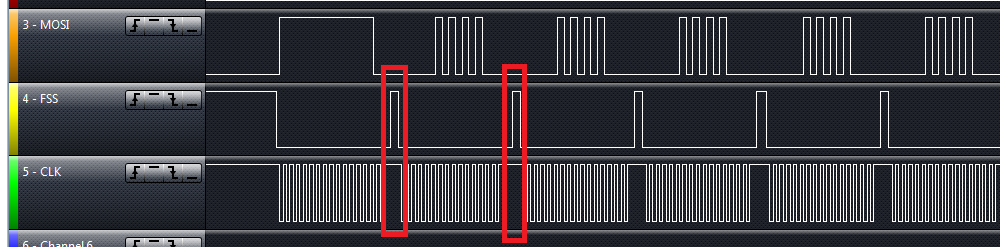
  

2. During transfer, I always keep SSI FIFO not empty. I think it will work in continuous model.

3. How can I make SSI work as continuous back-to-back transmission mode? I can’t see any configuration register to do it.


Best Regards.

Thank you.

TritonZhang.

  • More a set of observations than a solution I'm afraid.

    I've not spent a lot of time investigating FSS behavior on the TI micros but my observation on others has led me to the conclusion that SPI peripheral select is useless (sometimes worse) as a select line in master mode.

    Sometimes it only works as a slave select, so if I have spare I/O I will simply put a pullup on the signal.

    Even if it is not slave select only the spi peripheral's concept of frame is often the length of the word so it's useless if the frame is longer than a few bytes.

    I do agree the documentation suggests that the spi peripheral understands the concept of a frame but my quick overview didn't show a way to set the frame size.  Admittedly I wasn't looking.

    You may need to do the select control manually.

    Robert

  • I did a little more reading. The documentation states the select should stay low for "back to back" transfers.   However it neglects to mention what qualifies as a "back to back" transfer.

    I think some clarification might be useful.

    Robert

  • Triton Zhang said:
    3. How can I make SSI work as continuous back-to-back transmission mode? I can’t see any configuration register to do it.

    I agree that the documentation doesn't make it clear what triggers the SSI to work as "continuous back-to-back transmission mode". My guess is that the "back-to-back" transmission continues until the SSI FIFO is empty.

    E.g. using a LM4120H5QR initialised SSI2 to use the FSS output in Freescale-3 mode with the following code:

        MAP_SysCtlPeripheralEnable(SYSCTL_PERIPH_GPIOB);
    
        // Initialise the SSI we will use for communication with the LED Matrix:
        //    PB4 - SR_SCLK
        //    PB5 - SR_LATCH
        //    PB7 - SR_DATA
        MAP_SysCtlPeripheralEnable(SYSCTL_PERIPH_SSI2);
        MAP_GPIOPinConfigure(GPIO_PB4_SSI2CLK);
        MAP_GPIOPinConfigure(GPIO_PB5_SSI2FSS);
        MAP_GPIOPinConfigure(GPIO_PB7_SSI2TX);
        MAP_GPIOPinTypeSSI(GPIO_PORTB_BASE, GPIO_PIN_4 | GPIO_PIN_5 | GPIO_PIN_7);
    
        // Configure the hardware SSI module.
        // SSI_FRF_MOTO_MODE_3 is used so that the FSS is used to latch the data in the
        // display automatically at the end of the transfer.
        MAP_SSIClockSourceSet (SSI2_BASE, SSI_CLOCK_SYSTEM);
        MAP_SSIConfigSetExpClk (SSI2_BASE, MAP_SysCtlClockGet(), SSI_FRF_MOTO_MODE_3, SSI_MODE_MASTER,
        		                4000000, 16);
        MAP_SSIEnable (SSI2_BASE);
    

    The code transmits six 16-bit words every millisecond using the following loop:

        for (moduleIndex = 0; moduleIndex < NUM_LED_MODULES ; moduleIndex++)
        {
        	txData = (128 >> ledModuleColumnIndex) | (ledModuleData[bufferIndex][moduleIndex][ledModuleColumnIndex] << 8);
            MAP_SSIDataPut(SSI2_BASE, txData);
        }
    

    The majority of the time the 96 bits are transmitted back-to-back as expected, where FSS stays low during the transmission:

    However, sometimes there is a "gap". E.g. 64 bits transmitted with FSS low, transmission halts for ~5 microseconds with FSS high followed by the transmission of the remaining 32 bits with FSS low:

    In my case I think an interrupt is sometimes occuring during the loop writing to the SSI Tx FIFO such that the FIFO goes empty part way through the data such FSS goes high during the transmission. Will try using DMA to write the set of six 16-bit words to the SSI Fx FIFO to see if that makes the transfer reliable.

    Triton Zhang said:
    2. During transfer, I always keep SSI FIFO not empty. I think it will work in continuous model.

    What is the code which keeps the SSI FIFO not empty, and what is the value of SPI_SPEED_MASTER?

    [The higher the SSI clock frequency the more quickly the software must write to the SSI FIFO to stop the FIFO going empty during a transfer]

  • Chester,

    Thank you for your answer.

    I think I have found the root cause for this issue.  my code as below:

    for (i = 0; i < ulCnt; i++)   {     

        ROM_SSIDataPut(ulSSIBase, *ulVal++);     

        ulTimeout = 0x3FF;     

        while (ROM_SSIBusy(ulSSIBase) && (ulTimeout--));     

        if (!ulTimeout) {return FLAG_ERROR;}

     }   

     In order to ensure very data be transfer successfully, I will check the SSI Busy flag.  I think the red marked code cause FSS pin be plused high.


    Thank you very much.

    Best Regards

    Triton.Zhang


  • Triton Zhang said:
     In order to ensure very data be transfer successfully, I will check the SSI Busy flag.  I think the red marked code cause FSS pin

    The code structure waits for one word to be transfered before writing the next one into the SSI FIFO. That explains the observed problem where the FSS goes high after each word. The SSIDataPut function blocks until there is space in the SSI Tx FIFO. Therefore, there is no need to call SSIBusy inside the loop which transfers each word.

    Therefore, suggest either:

    1. Remove the test on SSIBusy, if the code doesn't need for the entire transfer to complete before continuing.
    2. Move the test on SSIBusy to after the loop has written all the data to the SSI Tx FIFO, if the code needs to wait for the entire transfer to complete before continuing.
  • Chester,

    Yes, I moved SSIBusy to after the loop, Thank you!


    Best Regards

    Triton


  • Chester Gillon said:
    In my case I think an interrupt is sometimes occuring during the loop writing to the SSI Tx FIFO such that the FIFO goes empty part way through the data such FSS goes high during the transmission.

    As a quick test to prove it was an interrupt which was causing the problem, added code to disable interrupts around writing to the SSI Tx FIFO:

        UInt     intKey;
    
        intKey = Hwi_disable ();
        for (moduleIndex = 0; moduleIndex < NUM_LED_MODULES ; moduleIndex++)
        {
        	txData = (128 >> ledModuleColumnIndex) | (ledModuleData[bufferIndex][moduleIndex][ledModuleColumnIndex] << 8);
            MAP_SSIDataPut(SSI2_BASE, txData);
        }
        Hwi_restore (intKey);
    

    This prevented the ocassional problem of the FSS ging high during a transfer, but the downside is that processor interrupts have to be disabled for the duration of the transfer.

  • That's a trifle fragile.  A good reason to avoid using FSS IMO.  Maybe time for uDMA?

    More complex to set up, but it has the additional benefit of reducing CPU time spent servicing the peripheral. Not at all sure the savings outweigh the cost in this case.

    Robert

  • Robert Adsett said:
    Maybe time for uDMA?

    More complex to set up

    As an example modified the code to use uDMA. Had to add some buffers:

    // Buffer used to transmit by DMA one LED module refresh
    uint32_t ledModuleDMATxBuffer[NUM_LED_MODULES];
    
    //*****************************************************************************
    //
    // The control table used by the uDMA controller.  This table must be aligned
    // to a 1024 byte boundary.
    //
    //*****************************************************************************
    #if defined(ewarm)
    #pragma data_alignment=1024
    uint8_t ui8ControlTable[1024];
    #elif defined(ccs)
    #pragma DATA_ALIGN(ui8ControlTable, 1024)
    uint8_t ui8ControlTable[1024];
    #else
    uint8_t ui8ControlTable[1024] __attribute__ ((aligned(1024)));
    #endif
    

    The initialisation code changed to:

    	MAP_SysCtlPeripheralEnable (SYSCTL_PERIPH_UDMA);
    	MAP_uDMAEnable();
    	MAP_uDMAControlBaseSet (ui8ControlTable);
    
        MAP_SysCtlPeripheralEnable(SYSCTL_PERIPH_GPIOB);
    
        // Initialise the SSI we will use for communication with the LED Matrix:
        //    PB4 - SR_SCLK
        //    PB5 - SR_LATCH
        //    PB7 - SR_DATA
        MAP_SysCtlPeripheralEnable(SYSCTL_PERIPH_SSI2);
        MAP_GPIOPinConfigure(GPIO_PB4_SSI2CLK);
        MAP_GPIOPinConfigure(GPIO_PB5_SSI2FSS);
        MAP_GPIOPinConfigure(GPIO_PB7_SSI2TX);
        MAP_GPIOPinTypeSSI(GPIO_PORTB_BASE, GPIO_PIN_4 | GPIO_PIN_5 | GPIO_PIN_7);
    
        // Configure the hardware SSI module.
        // SSI_FRF_MOTO_MODE_3 is used so that the FSS is used to latch the data in the
        // display automatically at the end of the transfer.
        MAP_SSIClockSourceSet (SSI2_BASE, SSI_CLOCK_SYSTEM);
        MAP_SSIConfigSetExpClk (SSI2_BASE, MAP_SysCtlClockGet(), SSI_FRF_MOTO_MODE_3, SSI_MODE_MASTER,
        		                4000000, 16);
        MAP_SSIEnable (SSI2_BASE);
    
        // Configure DMA to perform the SSI Tx so that a back-to-back transfer occurs with FSS asserted for the entire transfer
        MAP_SSIDMAEnable (SSI2_BASE, SSI_DMA_TX);
        MAP_uDMAChannelAssign (UDMA_CH13_SSI2TX);
        MAP_uDMAChannelControlSet (UDMA_CH13_SSI2TX, UDMA_SIZE_32 | UDMA_SRC_INC_32 | UDMA_DST_INC_NONE | UDMA_ARB_1);
        MAP_uDMAChannelTransferSet (UDMA_CH13_SSI2TX, UDMA_MODE_BASIC,
        		                    ledModuleDMATxBuffer, (void *)(SSI2_BASE + SSI_O_DR), NUM_LED_MODULES);
    

    And the code to generate one transmission changed to update the DMA Tx buffer and then trigger the DMA:

        // Write update to DMA Tx buffer
        for (moduleIndex = 0; moduleIndex < NUM_LED_MODULES ; moduleIndex++)
        {
        	ledModuleDMATxBuffer[moduleIndex] = (128 >> ledModuleColumnIndex) | (ledModuleData[bufferIndex][moduleIndex][ledModuleColumnIndex] << 8);
        }
    
        // Trigger a DMA Tx. As the update rate is slower than the time to transmit the buffer
        // don't wait for the Tx to complete.
        MAP_uDMAChannelTransferSet (UDMA_CH13_SSI2TX, UDMA_MODE_BASIC,
        		                    ledModuleDMATxBuffer, (void *)(SSI2_BASE + SSI_O_DR), NUM_LED_MODULES);
        MAP_uDMAChannelEnable (UDMA_CH13_SSI2TX);
    

    Robert Adsett said:
    That's a trifle fragile.  A good reason to avoid using FSS IMO. 

    Agree. With the uDMA used to perform the "back-to-back" transfers the SSI transmission "appears" to operate without any obvious glitches. However, as the SSI is just used to refresh a LED matrix if the FSS did de-assert during a transfer you wouldn't know unless happened to notice a "flicker" on the display.

    The datasheet for a Tiva device states that:

    When the uDMA controller arbitrates for the bus, the processor always takes priority. Furthermore, the uDMA controller is held off whenever the processor must perform a bus transaction on the same bus, even in the middle of a burst transfer.

    It is not obvious if there are some conditions where the processor could prevent the uDMA controller from obtaining access to the bus for long enough to cause a SSI Tx to fail to perform a back-to-back transfer. I would be wary against using the back-to-back SSI with uDMA to implement a transfer which needed a reliable transfer without some idea of the available bus-bandwidth to the uDMA controller channel.

  • In the past on Stellaris parts w/o uDMA, I was able to keep the SSI saturated by having the transmission handled in an interrupt.  In the interrupt I would send data until the TX FIFO was full, then return.  on the next interrupt I would send more data.  This meant I did not have to do busy waits with interrupts disabled, potentially impacting other interrupts in the system.

    Alternatively, you can control FSS manually (make the pin GPIO controlled), and then your transmissions will work regardless of delays between frames.