This thread has been locked.

If you have a related question, please click the "Ask a related question" button in the top right corner. The newly created question will be automatically linked to this question.

Read large number of samples from ADC at max sampling rate

Other Parts Discussed in Thread: TM4C123GH6PM

I'm working with the Tiva C Launchpad board which uses the TM4C123GH6PM microcontroller.  I'd like to be able to read a large number of samples (say, 128) from the ADC at its full rated speed of 1 MSPS.  The samples need to be read with a constant 1 us time spacing, as should be the case for a 1 MSPS sampling rate.

First off, is this possible using this hardware?  If so, what would be a good strategy to pull this off?  What would I need to do to transfer the data to memory at the appropriate speed to keep up with the ADC?  I'm pretty new to microcontrollers, so any help would be appreciated!

  • Austin Spencer said:
    ...able to read a large number of samples (say, 128) from the ADC at its full rated speed of 1 MSPS.  The samples need to be read with a constant 1 us time spacing, as should be the case for a 1 MSPS...

    "Should be the case" for one sequence sample - not 128 - back to back - as your writing seems to suggest. 

    Closer reading of MCU's spec fails to state that such 1uS, ADC sampling time spacing - can be "productively" maintained, (ad infinitum) into any/all following sequence samples!  (hopeful/wishful thinking, aside)

    Attempting such a, "multi-peripheral goal" - based upon the optimum  performance  (and limited scope) of just a single peripheral - usually is not destined for success. (i.e. you have to harvest the ADC's data, transfer to memory, likely "move and/or process" that data, and re-trigger the ADC)  Achieving all that - and assuming other "normal/customary MCU function management" - w/in your spec'ed time constraint - unlikely... 

    The proper "relaxation" of your goal - to better "mesh w/reality" - may warrant consideration.  While you ask if your goal is realizable - you provide little guidance as to care/handling - subsequent use/transport of your 128 sampled, ADC data... 

    There are quite good (and detailed) posts here describing uDMA and its link to MCU's SRAM & ADC.  Automating your process in that/similar manner - while adding SW design complexity up front - may yield results closest to your goal...

  • Thanks for the input.  This is exactly why I asked whether or not this plan would be realizable given the hardware constraints.  I don't want to sink a load of time into a task that is doomed from the start.  However, I do have a few follow-up remarks.

    It seems a waste to outfit the MCU with such a fast ADC without the ability to take a meaningful number of samples at that speed.  For instance, if someone wanted to FFT a time series collected from the ADC, they would be limited to 8 samples (the largest sequencer size) since that would be the maximum number of samples with a known constant sample rate, which is too small to be useful.

    I thought that perhaps, given that the MCU can run at a clock rate of up to 80 MHz, the MCU could use the 80 cycles between ADC samples to move a single ADC sample into memory and then retrigger the ADC for the next sample.  I don't really need the MCU to do anything during data collection besides store the ADC samples.  All processing of the samples can occur afterwards when there are no time constraints.

    I'm probably just trying to use this device outside of its expected use case, but if it were able to provide a constant sample rate for more than 8 samples, this device would be a nice all-in-one solution for a load of applications.

    Thanks again.

  • Hi,

    You should use DMA to transfer the samples from the ADC into memory. You might want to look at the famous "Euphonistihack's frequency analyzer" project. I'd especially look at this file:

    https://github.com/EuphonistiHack/launchpad-freq-analyzer/blob/master/StellarisWare/boards/ek-lm4f120xl/freq_analyzer/freq_analyzer.c

  • We don't know if some reduction in a 1 Msps rate truly causes your, "all in one" solution to fail.  That said - w/out undue difficulty - you may exploit the 2nd ADC module (assumes MCU selected includes such) to delay its sampling by 22.5° - and effectively double the sampling rate of an input.  (ADC Sample Phases chapter in our past, LX4F MCU manual details)

    Note that follow-on poster repeats our earlier uDMA suggestion - and done properly - this better enables the MCU to perform other tasks. 

    Yet another method - used by our group in an industrial application - employs multiple MCUs and independent, higher performance, dedicated ADCs - serving to maximize analog data acquisition speed & accuracy.

    You'll learn much thru such experimentation - charting and comparing your results under a variety of strategies/methods.

    If you can avoid disappointment/frustration caused by an "unrealistic" goal - effort may even prove fun...

    And - perhaps adding some challenge to your, "use of MCU cycles between" ADC reads:

    Note that latency is a, "nominal" - and the trigger itself may not be fully predictable - under all circumstances/operating demands/conditions...


  • Hi Austin,

    Yes, at 80Mhz there are more than enough spare cycles to keep up with the ADC running at 1MS/s. Just avoid using driver library functions (or use with care) - you don't have unlimited cycles.

    The ADC can write to FIFO 0 which has space for 8 samples.

    You set the ADC going, then you read samples from the FIFO as fast as possible into your array (limited only by available memory). So you can have runs of 2048 or more if you want. There is an ADC 'continuous sampling mode' but I don't know how accurately the samples are spaced in time. You can use a timer to trigger the ADC instead.

    You need to check the FIFO 'overflow' flag which tells you whether you are keeping up with the ADC. Otherwise the ADC simply overwrites samples and you don't have any data integrity.

    DMA is the most efficient and elegant solution, but it might be a useful exercise to do it by 'brute force' first as above to see how things work.

    You may get a little less than 1MS/s but there are two ADC's to play with.

    Jim

    ----

  • Jim_McCormack said:
    Yes, at 80Mhz there are more than enough spare cycles to keep up with the ADC running at 1MS/s.

    Stated with authority - but w/out any supporting calculations or operating conditions - to justify/verify.  Our group - potentially many others - would benefit from the analysis which enabled such, "rock-solid" conclusion.  And - do recall that poster seeks 128 such ADC reads & handlings - each/every one w/in that strict, 1uS time-slot...

    And - might the MCU have other functions/objectives - and would not their satisfaction potentially intrude upon your, "blue-sky" assertion? 

    Real world needs/demands have nasty habit of disrupting, "hopes/dreams," even well defined (i.e. well calculated) ones. 

    No effort has been made to justify the "criticality" of 1Msps.  Faster is not always - under all conditions - better...

  • Hi cb and Austin again,

    cb makes a very fair point, I may simply be quoting from the microcontroller data sheet which you can read yourself!  But ...

    I have been experimenting with the ADC module, and I have set up five different ways so far to do what Austin is after, and there is a lot more for me to learn about the ADC module.

    I saw Austin's post and didn't want him to give up on these devices - so far I have little doubt he can collect samples at 1MS/s or near, BUT I don't know (yet) how accurate the results are either in time or 'effective' bits.

    The structure of the ADC can be a little confusing at first as it is really intended (as far as I can judge) for recording a whole load of sensors at once, not for measuring one or two signals. I suppose if you want the latter, a DSP device is what you are after if speed is the issue, but the M4F/TivaC looks like a great general purpose device, and it has a quite fast ADC capability for this kind of device.

    Now, to provide a little bit of hard data on the simplest approach (no interrupts, no DMA, running at 80MHz) :-

    I set ADC0 running in 'continuous sampling' mode, option 1MS/s, writing into queue/buffer FIFO 0 (8 samples max).

    My 'inner loop' reading samples from FIFO 0 into my array unsigned short [1024] is basically just a couple of C statements. Looking at the assembly code in the debugger this is only 7 instructions. This is a bit of overkill and the C library calls would probably do the job fine. This leaves a lot of cycles spare. How many? The problem is that above 40MHz flash read is not single cycle and is buffered. So I inserted a SysCtlDelay(nd) after reading each sample to get an idea how many cycles could be inserted before suffering a FIFO overflow (see bits 0-3 in ADC_O_OSTAT). I get overflow with nd=18, so this represents quite a lot of cycles (18x3+a few more, though likely fully buffered), enough to read the other ADC at the same time and more.

    I collect 1024 samples in a run, with the ADC on a nominal '1MS/s'. With a timer I am reading  exactly 81999 or 82011 ticks, or a real sampling rate of 999036 or 998890 S/s. Why there should be 12 ticks difference I don't know, but I note that the ADC latency is quoted as nominal 2 ADC clock cycles (at 16MHz), or 125ns, maybe the ADC truncates to a 125ns boundary, just a thought, still not 12 though!

    I am using an internally generated PWM test signal of 50KHz with duty cycle from 10 to 90%.

    So, it seems that the samples can be collected no problem.

    I could be doing something dumb e.g. I am assuming that reading the FIFO whilst the ADC is sampling continuously does not require any synchronization, I haven't seen any cautions on this, and the ADCSequenceDataGet library function does the same. You can use other methods though.

    What about the accuracy of the results, time-wise and bit-wise? I can't really say yet, hence my reluctance to say too much in my previous post!

    The data sheet says 1MS/s and I am seeing nearly exactly that on the average, but I would like to fire a proper test against it. The very precise readings for timing (only one of two values) would tend to suggest that the ADC must be clocking very consistently on 1us with no jitter in time, otherwise why do I not see some variation of at least a few ticks? But maybe my limited tests so far are leading me astray, more to do here.

    For signal 'high' on the PWM test signal, the 'error' looks like two bits or so, but the signal is going out of the board and in again, any old way (no analog design at all), so how much of this 'error' is the variation on the signal, or ADC error, I don't know yet. The signal on low is worse, I don't know why, maybe the charge needs help draining away, or maybe for low readings the ADC is worse. Work to do, but so far, it looks more than good for my purposes.

    Please do point out any blunders if you spot any, I am new to Stellaris/ARM/32-bit MCU's (but quite old in many other areas!). I don't wish to lead anyone down a dead-end.

    Hope this is of some help ...

    Jim.

    ----


  • @ Jim,

    Very well done - imho "starts a dialog" - long missing in MCU-ADC's, "care/handling application" - especially at (or near) limits. 

    Believe you have identified many/most of the critical issues - and you've presented w/great care & detail.  Thank you - your writing sure to benefit many...

    Long past - I attempted a similar methodology - trying to "unlock" those aspects of the MCU's ADC operation which escaped the MCU manual.  (and every related post - which I could find here)  As we use multiple ARM MCUs - from multiple vendors - I ran this test against/across many ARM devices.

    Like you - the choice of input signal was deemed critical.  Constant voltage signal proves of minimal value - could we someway/somehow create a signal which would:

    a) "sync" (either by skilled design or good fortune) to the individual "steps" w/in the ADC's Step Sequence
    b) ramp (both up/down) so that alleged (hoped for) sync could be proven and the conversion accuracy could be judged
    c) quickly "level shifted" - so that any "charge residue" upon the ADC's input C (and/or other issues) could be quickly/easily recognized

    While not complete - believe this design was/remains logical - and when implemented w/skill & precision - harvests "real ADC data" - most valuable - yet currently unavailable!

    Under "blue sky" (i.e. no other interruping, or otherwise higher priority operations diverting) we charted results.  And - when "normal/customary" MCU operation was enabled/restored - these earlier, ADC results varied.   So  I believe actual "real-world" MCU operation must be considered. 

    Suspect that use of these methods (or extended and/or better ones) will aid our ARM community when, "squeezing every last drop of MCU-ADC performance" is the objective.   And you & I - triggered by op - have made our contributions - in that regard...

  • Jim,

    Wow, thanks a lot for the help and for going all the way into testing a solution!  I'd like to try it out but I'm not sure how to put the ADC into continuous mode (even after reading the datasheet) or exactly how you're reading the ADC result.  I've just used the provided ADC libraries so far.  Would you mind sharing the code that you tested this with?

    Thanks,

    Austin

  • " for going all the way into testing a solution!"

    @ Jim - feared that real effort (study/experimentation) would fall victim to, "cookbook" (effort-lite) mentality...

    Having "some time" @ this forum (several others) - floodgates may open - too often minus proper appreciation.  Know what you may be getting into - should you engage/encourage such "effort-free" requests.. 

  • Effort-free requests?  Don't flatter yourself into thinking that you know me at all.  If you pay attention to my posts, you'll notice that I never asked for someone to write code for me.  I sincerely appreciate Jim's effort in showing that what I want to do is possible.  I'm a scientist, so I appreciate when scientific scrutiny is carried out before conclusions are made.

    Now, if you look into any textbook on programming, you'll notice a lot of code examples.  This is because people find them helpful in learning.  Concepts are nothing without concrete examples.  Are these code snippets "cookbook" solutions?  No.  You still have to modify them and extend them to fit your needs.  So, I say that learning from small pieces of example code is important.

    If Jim wants to share the specifics of his work, that's up to him.  What I know is that this type of input is very helpful to beginners such as me who are interested in learning, not just copying.  I will likely need to at least slightly modify and extend any such example code to fit my needs and can use the ideas gleaned from it for future projects.

  • Austin Spencer said:
    know me at all.

    No such flattery was sought - deliberately chose not to, "attach any name to quote" - suggestion was thus advanced as, precautionary and in, "general."

    This rebrand family - and its predecessors - have achieved success (our group/many others believe) due to the great detail and number of, "example programs." 

    Facts in evidence - your  posts here (this thread) - failed to reveal your willingness to make serious effort.   Your most recent post counters that impression. 

    A fair reading of my post reveals that I am encouraging multiple others - who really want to - or may require such specific ADC detail - to continue and/or "expand/improve upon" my past efforts.  Flattery (real or imagined) aside - I did provide substantial guidance - to both you & others...

  • cb1,

    Thanks for the clarification.  I agree that "cookbooking" is not always a good practice for teaching and learning.  I came to this "Support Forum" for support and guidance, and I appreciate any that I receive, however detailed.  I think it's important to understand that people come here to ask for help, which takes many forms depending on the individual, and they should be encouraged to do so.  It's clear that you have a lot of knowledge in the subjects covered here, whereas many of us are newcomers and things that seem to you like simple code handouts might be quite instructive to those with less experience.

  • @ Austin,

    May be that you/I have "cooler heads" than hallowed/always respected leaders in/around Wash, D.C. 

    I do try to assist - several forums - "pay back" help I received (and continue to receive).

    This forum - by far, "best in class."  And - several of us have been here from beginning - have invested substantial time/effort.  (tech & legal: boiler plate "protections" (base, this forum) for outside, "providers of content" - much due, my efforts...)

    So - "do my homework" and "effort-lite" requests - rankle - quite properly, I submit.  And neither is your case.

    To your specific - our group had much same issue as you reported - and while I've had some success (co-founded, took tech firm public)   encouraging ideas/efforts of others - most always yields best/fastest results.  And - I quite deliberately provided my past "method" as a beginning "roadmap" - intended to interest/invite & seriously involve dedicated & resourceful others. 

    Thus - any intruding "cookbook" would likely derail that effort.   And in no way doubting Jim's skills/efforts - I strongly believe that this subject is complex enough that a "group contribution" - most always yields best/brightest/fastest results...   (cookbooks - not so much - and encourages (blots the plain) w/too many, "effort-lite" poorly prep'ed/considered requests.  (surely, none yours)

  • Hi again Austin,

    My application uses five different methods with flags to switch between them, so, aside from any other considerations, it is too long/complicated, and not very useful for showing the basics!

    It sounds from what you have said that you should start with the driver lib functions and avoid working with the MCU registers yet, which can be very obscure to start with.

    Just use ADCSequenceDataGet() to grab samples in batches, and copy them to your array. There is a library function to check for FIFO overflow. I think I got this to work at 30MHz for 1MS/s. Be sure to empty the FIFO (using ADCSequenceDataGet) before you start a new run.

    There are lots of basic examples in these groups, e.g. see http://e2e.ti.com/support/microcontrollers/stellaris_arm/f/471/t/211849.aspx - change ADC_TRIGGER_TIMER to

    ADC_TRIGGER_ALWAYS, drop the ADC_CTL_IE, once you do ADCSequenceEnable() the ADC is running. You will need SysCtlADCSpeedSet (the default on my device is 125KS/s). Forget the rest of this example.

    But, how will you measure what you get? You might need to work with timers first?

    The slowest speed for testing is 125KS/s in this mode. I started with one sample every 5 seconds (0.2S/s) to get a feel for how the ADC and FIFO work together, you can just watch things happening in real time  !...


    Jim

    ----


  • Jim,

    Thanks, that's just what I needed to get started.  I have it running now and I can get at least 1024 samples at what is essentially 1 MSPS.  I'm using the Tivaware library functions to setup and read the ADC, so they appear to be fast enough with the core clocked at 80 MHz.  To read the ADC, I run this line in a while loop which stops when the array of ADC samples is full:

    ui32ReadIndex += ROM_ADCSequenceDataGet(ADC0_BASE, 0, &ui32SampleArray[ui32ReadIndex]);

    I'm not sure how standard this method is, but it appears to work well enough.  Another key was to increase the stack and heap sizes above their default values (when reading >256 samples) because otherwise I would get a mysterious interrupt that would halt operation without much indication of what went wrong.

    Thanks again for getting me started on this.  My next step will be to try to run both ADCs simultaneously to get 2 channels of input.  Also, any hints on where to look for a simple method to transfer the ADC data to a PC for plotting?  Using the UART and a console program works, but it's not quite as customizable and programmatic on the PC end as I'd like.

    Austin

  • Austin Spencer said:
    I can get at least 1024 samples at what is essentially 1 MSPS

    While bit surprising to me - very good news for you.

    Might you provide some detail as to how you assured yourself that all 1024 "unique" samples arrived - and were processed & stored - in "essentially" 1.1mS?  Am not seeking any code - simply some description of your method to support your capture & store of 1K (legitimate) samples w/in that timeframe...  (i.e. "normally" ADC code examples show the requirement to, "wait for conversion to be completed" - prior to ADCSequenceDataGet() - which we don't find w/in your code loop...)

    " ui32ReadIndex += ROM_ADCSequenceDataGet(ADC0_BASE, 0, &ui32SampleArray[ui32ReadIndex]); "

    As you seek to use this MCU/method in a scientific endeavor - my wish is that your data captures are both timely and "real." 

    Our method - of providing a linear, known, ramping voltage - spanning 0V36 - 2V93 (derived via 3V3/9) over the 8 sequence steps - at best achievable ADC rate - likely better highlights "illegal captures" - which may pass thru "undetected" if a constant voltage - or one changing at far slower (dV/dt) rate - and unqualified by, "conversion's completion" - is employed/attempted...

  • Hi Austin,

    That looks pretty handy for collecting the samples, and if you are getting '1MS/s', and the data look sensible, perhaps this is sufficient for your needs.

    cb is right to ask some questions, e.g. whether the FIFO queue/buffer can be read in 'non-synchronous' fashion, e.g. you may introduce some some jitter time-wise? I don't know myself yet.

    If you want to synchronize with the ADC's 'sample ready' flag (e.g. using ADC_CTL_IE + ADCIntStatus()), you may need a tighter 'inner-loop' for collecting samples (reading the FIFO registers directly).

    How does the FIFO work, what is the locking mechanism? The data sheets for these MCUs are already typically 1200+ pages, and whilst I would like to see more detail (e.g. closer to 2500 pages+!), I can see the problem. There is just too much functionality packed in to these chips.

    A 'read' is actually a FIFO 'update' operation, i.e. the value 'read' is removed from the FIFO. If you are reading (extracting) a sample from the FIFO and the ADC has a new sample ready, does the ADC have to 'spin' for a few MCU clock cycles?

    If it does, this could mean some jitter time-wise in a few (maybe just a very few) of your samples, whilst your average would still be indicating 1MS/s. 

    Or worse still, is there a risk that a sample gets dropped/corrupted if there is a conflict? (this seems rather unlikely to me, but again I don't know yet).

    Of course, there are other ways to do it, or you could do some measurements to validate your samples, or maybe this is 'good enough' for your needs?

    When I used 1MS/s continuous mode (i.e. with ADC_TRIGGER_ALWAYS) I found that it didn't work above 1200 samples or so in one run. I didn't look into what the problem was. Maybe you could try 2048 samples in one run and see if it works? I would be interested to know ...

    Jim

    ----


  • Jim_McCormack said:
    How does the FIFO work, what is the locking mechanism? The data sheets for these MCUs are already typically 1200+ pages, and whilst I would like to see more detail (e.g. closer to 2500 pages+!), I can see the problem. There is just too much functionality packed in to these chips.

    Immediately upon reading this I had a flashback from shuffling through the datasheet. Look at ADC registers 5 and 7 (FIFO Overflow & Underflow Status). From what I understand, they're not self-clearing, so if at the end of the read sequence you would check those and they're all zeros, you should have all samples safely collected. I haven't tested this, posting as a quick observation only.

    Regarding whether the ADC would need to "spin" on FIFO access, I don't think that would be a problem; look at 13.3.2.5 - Sample Phase Control. There seems to be ample "leisure time" built into the workings of the ADC. Again, unverified. Btw, you can nicely see the connection between max. ADC sample rate of 1MS/s and the minimum clock requirement of 16 MHz right there.

  • cb1,

    You bring up some reasonable concerns.  I haven't had a chance yet to thoroughly test my code, but I will report on that once it's been done.

    What I have done so far is use the SysTick counter to see how many MCU cycles it takes to acquire some number of samples.  I then use the following equation to estimate the effective ADC sampling rate:

    (ADC sample rate) = (MCU frequency) * (# of ADC samples) / (# of MCU cycles)

    For 1024 ADC samples, I get on the order of 82000 MCU cycles with a MCU frequency of 80 MHz.  Plugging that into the equation above, you should get ADC sample rate of ~0.999 MHz.  I expect that this is slightly under 1 MHz due to there being some overhead in enabling SysTick before the ADC loop and reading the SysTick count after the ADC loop.

    As for samples being unique and without time jitter, all I can say so far is that the samples are not artifactual in any obvious way.  Just taking samples without any input test signal (basically just measuring whatever electronic noise is present), they appear to be unique from sample to sample and I see no repeating patterns.  This doesn't say much about how accurate the samples are with respect to voltage or timing, but it at least makes me believe for the time being that they are not complete junk.

    Again, I know more testing is necessary to be sure about my results, so I'll get back to you once I've had a chance to put some serious test signals into it.

    Austin

  • Jim_McCormack said:
    If you want to synchronize with the ADC's 'sample ready' flag

    Much favor Jim's desire for more - rather than less - scientific rigor to accompany this, "secret unlocking" w/in the ADC.  And indeed the MCU manuals are long - but further detail - at least in this subject area - appears very helpful.

    Here - suggestions which may guide our present thread group (& hopefully attract others):

    a) we employed a semi custom, very fast DAC (i.e. expensive) - to provide linear, stepped, ramped voltages in the attempt to discover just when the ADC actually performed its step-sequenced, analog captures

    b) as not many will have such hi-perfomance, DAC access - we hit on the idea of producing progressively narrower digital pulses (injecting these into the ADC) - and seeing: if, how, when & where these were captured by  the ADC (i.e. where they appeared {if they appeared} w/in step-sequence)  These have no analog value - but serve as a controllable "marker" - to help identify "where in the ADC process" the input signal is actually captured.. (and proved both revealing & surprising)

    c) refining (b) - we produced a 3 pulse train - "hi-lo-hi" (or its inversion) which enabled independent adjustment as to: launch from known trigger and width of each pulse

    d) while mentioned w/in the MCU manual - the fact that, "ADC_CTL_IE" may be included anywhere w/in the step-sequence - & not confined to single entry - may also be of great value.  (i.e. monitoring of those interrupts may denote an actual, ADC capture or sequence of such "time-linked" ADC captures)

    e) and while (d) above appears attractive - just as when, "measuring the charge upon an electron" - how is that done w/out unduly, "contaminating" the measurement process?  May those interrupts "torment" our ADC time/place measures?

    Appears that, "cookbook" - has succumbed to: thought, plan, cause-effect analysis.  (suspect to the benefit of all, here)

    At some point - factory "inside info" commentary/guidance - would be nice arrival...

  • Well, I've finally gotten the time to really put the ADC through some tests.  My previous post mentioned the testing that I've already done to ensure the sampling rate is 1 MSPS, and I haven't seen anything since that contradicts that result. 

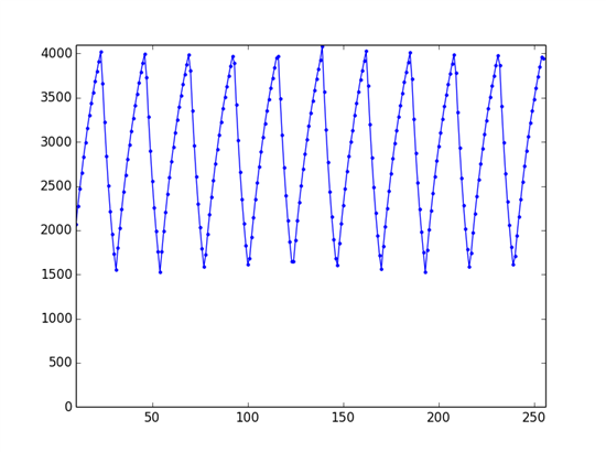
    I've played around with a 555 timer (set up as an astable oscillator) with frequencies in the range 10 kHz - 100 kHz and I've fed both the square wave and the triangle wave from the 555 into the ADC.  Consistency in the high and low time of the square wave was a good sign of consistent sample timing.  An even better test was looking at the triangle wave output of the 555 since a smooth rise and fall of the signal is a very strong indicator of a constant sample rate and, to some degree, accurate samples.

    Here's an example  waveform:

    This waveform was produced by the 555 oscillator and measured by the ADC sampling at 1 MSPS.  I'm using the MCU's UART to transfer data to a PC, where it is read using the serial library in Python and plotted with matplotlib.  You can see that the samples follow the expected pattern for a charging/discharging capacitor and there is no evidence of timing glitches.

    Of course, this isn't a universal solution for all fast-sampling needs/applications, but it appears to be good enough for what I want to do.  Hopefully some of this will be helpful to others also looking to push these MCU ADCs in terms of sampling rate.

    Ausitn

  • Hi Austin,

    That looks pretty good for many applications I suspect!

    I have some figures myself which I am going to post soon.

    Thanks for showing some results, I would be keen to see more later if you have the time.

    Jim

    -----