This thread has been locked.

If you have a related question, please click the "Ask a related question" button in the top right corner. The newly created question will be automatically linked to this question.

Selecting ADC cannel to be read.

Other Parts Discussed in Thread: HALCOGEN

Hello everyone,


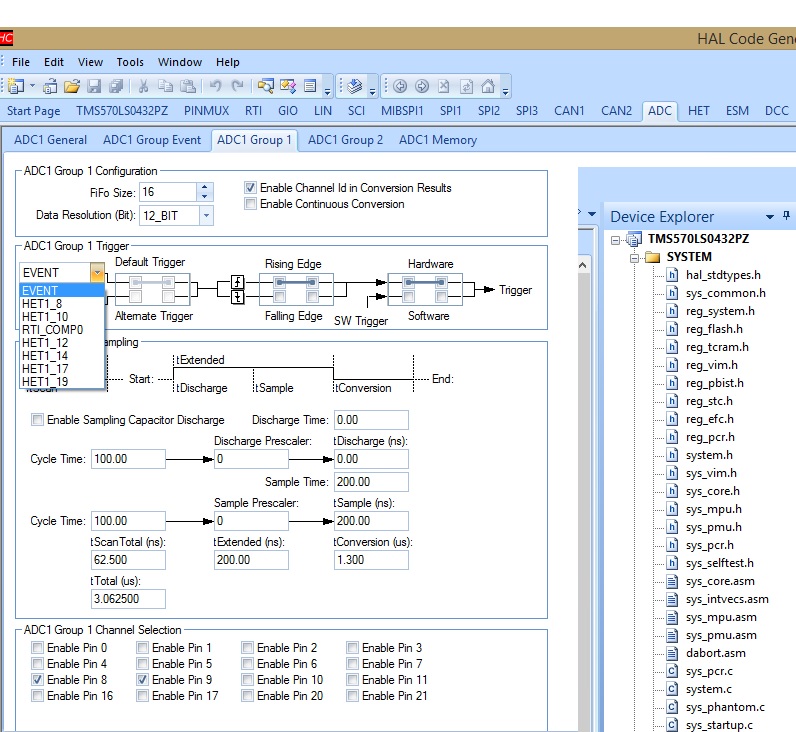
I am using the LaunchPad TMS570LS04x. Right now I'm trying the ADC module. I know how to configure it and work with one channel, however when it comes to use multiple channels, I do not know how to select a specific channel to read the converted value.

I enabled ADIN0 and ADIN9, then with the function adcGetData I read the converted value but I asume that the first time I call the function, I get the value from cannel 0 and the second time the value from channel 9. Is this assumption correct or is there a way to read the value of a desired channel?


Thank you in advance for your help.


  • Luis,

    Our ADC module has internal buffers used to store conversion result.
    On your device you have 64 buffers.
    These buffers are used by the 3 conversion groups: Event, Group1 and Group2.
    For each of these group you can select 1 or more channels to be converted.


    Halcogen provides a screen to define the split of these 64 buffers between the 3 groups as shown below:

    In this example, 0 buffer are assigned to Group event, 4 for Group1 and 60 for Group2.
    Each buffer handles the converted value, the ID of the channel converted and additional status bits.

    To convert more than 1 channel, use the following screen in Halcogen:

    Group 1 is configured to convert channel 8 and channel 9.
    Enable Channel Id in Conversion Results is checked. In addition to the converted value, the Channel Id will be stored in the buffer.
    The trigger used to start Group1 conversion is set to be GIOB0 rising edge.
    In this example, the GIOB0 will be set high and low to create the trigger condition.
    On each rising edge, Channel 8 and Channel 9 will be converted in sequence.

    Here is an extract from the test code:

            gioSetBit(gioPORTB, 0, 1);    // Create the rising condition to trigger Group1
            /* ... wait and read the conversion count */
            while((adcIsConversionComplete(adcREG1,adcGROUP1))==0);

            // Check how many conversion are done (Should be 2 in this example)
            // Also copy the converted result from ADC buffer to adc_data array
            ch_count = adcGetData(adcREG1, adcGROUP1,&adc_data[0]);
            id    = adc_data[0].id;        //Get Id for first conversion (8)
            Temp  = adc_data[0].value;     //Get Id for first conversion (8)
            id    = adc_data[1].id;
            Lamp  = adc_data[1].value;
            gioSetBit(gioPORTB, 0, 0);
            wait(0xFFFFF);

    I've also attached the project as ZIP file. It is running on a different board, but the main code can be reused as it is.
    Just use Halcogen to generate the startup and driver code for your part.

    Let me know if this example is useful.

    3554.Basic_ADC.zip


  • Hello Jean-Marc,

    Thank you for your reply, it was very useful. Apparently I was missing to check the box "Enable Channel Id in Conversion Result".

    Now it works, it sends the channel id and data to the terminal via SCI. However there is one more issue.

    When I change the input in one of the channels, the value of the other channel is modified too. For instance, I connect channel 0 to 3.3V and the value displayed in the terminal is 4095 as expected, but the value for channel 9, which corresponds to the ambient light sensor increases too in a considerable amount even when the conditions have not changed for the sensor. What could be the reason?

    Here's my code:


  • When I tried this example, I could not select GIO0 as trigger (see attached screenprint) The GIO pins were not in the list of selectable events.
  • Hello Jan,

    The reason why you couldn't find the GIOB0 in the trigger options is because the example provided by Jean-Marc was developed for a different board.

    I pressume you are using the Hercules LaunchPad as well. The MCU of the board doesn't have a port B. Even though, most of the code can be used to make your own code that runs on the LaunchPad.


  • Ah, ok. In that case, I'd probably have to set up a hardware trigger on a GIO pin, and run the code when the notification handler of that trigger is fired. Right?
  • I have been trying the specific example for the Hercules Launchpad in the HALCoGen help files (HALCoGen TMS57LS04x Help 3.06.00), HALCoGen/v03.06.00/examples/TMS570LS04x/example_adcDisplay.c even though the MCU of the board doesn't have a port B, that example contains the line 59: gioSetDirection(gioPORTB, 1); and ADC doesn't seem to be triggered by a GIO pin (no rising/falling edge in the code), even though help file says: "This is an example which describes the steps to create an example application which configures ADC to start conversion ona GIO trigger and display it over an uart " I'll need to investigate further. Possibly the example is stripped down for this processor but not all code/comments are adapted.
  • Hi Jan,

    You are correct the example was not ported 100%. The comments on the top of main function does not match the code.

    The comments say to configure SW trigger, which mean no GIO triggers are needed.

    Attached is the modified Example file, which will be in the upcoming HALCoGen releases.

    4863.example_adcDisplay.c

  • Ah, Yes. I checked the examples. References, to HW triggering and reacting on GIOB are removed.