Hi!
My frequency counter project is based on the wide-timer #3 input edge count mode. As a signal source I'm using a 6 MHz TCXO (± 25ppm). The signal is stable as I'm measuring it with a frequency counter instrument. I'm using the input edge count up mode with a 24 bit wide timer.
My application has an external time-gate input coming from TCXO RTC to provide a stable 1 Hz time gate. The external pin interrupt reads out the timer value and handles it over to a task which eventually sends it to the PC. The interrupt handler also zeroes the timer value register.
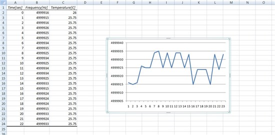
My problem is that I'm not getting consequent values (± 1 edge) but variance like:
5999956
5999967
5999945
5999956
5999956
5999944
5999945
5999956
5999956
5999956
5999967
5999956
5999955
5999955
5999944
5999944
5999955
5999944
5999933
5999956
5999944
5999944
5999955
5999933
The instrument however, shows no variance in the frequency so probably my method has flaws. Below is the relevant code and any help would be great as I'm probably misinterpreting something here.
#ifndef DEFCAPTURE_TIMER_H_
#define DEFCAPTURE_TIMER_H_

#define CAPTURE_TIMER_PH			SYSCTL_PERIPH_WTIMER3
#define CAPTURE_TIMER_BASE			WTIMER3_BASE
#define CAPTURE_TIMERA_INT			INT_WTIMER3A
#define CAPTURE_TIMERB_INT			INT_WTIMER3B

/* Edges to count from oscillator (5V tolerant!!!) */
/* WT3CCP0 - PD2 -#63*/
/* WT3CCP1 - PD3 -#64*/

#define EXTEDGE_PH SYSCTL_PERIPH_GPIOD
#define EXTEDGE_PIN_BASE GPIO_PORTD_BASE

#define EXTEDGE_PINA GPIO_PIN_2
#define EXTEDGE_PINB GPIO_PIN_3

#define EXTEDGE_PINA_CONFIG	GPIO_PD2_WT3CCP0
#define EXTEDGE_PINB_CONFIG	GPIO_PD3_WT3CCP1

#endif /* DEFCAPTURE_TIMER_H_ */

/***/

void Init_Capture_Timer_Pin(void){

	/*
	 * Enable and configure Timer input capture pins
	 */
	SysCtlPeripheralEnable(EXTEDGE_PH);
	GPIOPinConfigure(EXTEDGE_PINA_CONFIG);
	GPIOPinTypeTimer(EXTEDGE_PIN_BASE,EXTEDGE_PINA);
}

void Init_Capture_Timer(void){

	/*
	 * Enable Capture Timer peripherial
	 */
	SysCtlPeripheralEnable(CAPTURE_TIMER_PH);

	/*
	 * Configure 24 bit capture timer
	 */
	TimerConfigure(CAPTURE_TIMER_BASE, TIMER_CFG_A_CAP_COUNT_UP);

	/*
	 * Capture on positive edges
	 */
	TimerControlEvent(CAPTURE_TIMER_BASE, TIMER_A, TIMER_EVENT_POS_EDGE);


	/*
	 * Load and Match registers
	 */
	TimerLoadSet(CAPTURE_TIMER_BASE, TIMER_A, 0xFFFFFFFF);
	TimerMatchSet(CAPTURE_TIMER_BASE, TIMER_A, 0x00);
	/*
	 * Setup the interrupts for the timer timeouts.
	 */
	//IntEnable(CAPTURE_TIMERA_INT);
	//TimerIntEnable(CAPTURE_TIMER_BASE,  TIMER_CAPA_MATCH);

}

void Enable_Capture_Timer(void){

	TimerEnable(CAPTURE_TIMER_BASE, TIMER_A);
}

/***/

void TimeGateIntHandler(void){


	ui32EventCount = TimerValueGet(CAPTURE_TIMER_BASE, TIMER_A);
	HWREG(CAPTURE_TIMER_BASE + TIMER_O_TAV) = 0;

	GPIOIntClear(TIMEGATE_PIN_BASE, TIMEGATE_PIN);
	Task.Bits.FRQDRDY = 1;
}
/***/

void Task_FRQDRDY(task_t *tp){

	/*
	 * Count UP
	 */
	Init_UARTPCMSG_Struct((uint8_t*) &UartCPU2PC);

	UartCPU2PC.data = ui32EventCount;
	UartCPU2PC.tmp_int = ReadRTCSingleReg(RTC_TEMP_MSB_INT);
	UartCPU2PC.tmp_frc = ReadRTCSingleReg(RTC_TEMP_LSB_FRAC);

	tp->Bits.FRQDRDY = 0;
	tp->Bits.CPU2PC = 1;
	if (UartCPU2PC.data>4500000 && UartCPU2PC.data < 10000000) BlinkLED(GREEN);
		else BlinkLED(BLUE);
}


